Lair Of The Multimedia Guru

2017-11-19

DDR3 SO-DIMM in 2017

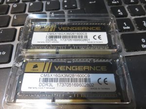
My notebook has 8gb ram and without swap occasionally that was not enough. So i thought hey trivial put more memory in. And while online resources disagreed on the maximum supported for my Acer Aspire V3-571G. It seems fine with 2 8gb sticks. But …
When running memtest (MemTest86 V7.4 actually, which was the first google pointed me to). It displayed after a while a note, “[Note] RAM may be vulnerable to high frequency row hammer bit flips”. After a short wtf moment, and a bit of research, this is a hardware bug that can be used to flip bits one normally has no access to and exploit an affected machine. I think i did actually read about it years ago but did not immediately connect the note message to it.
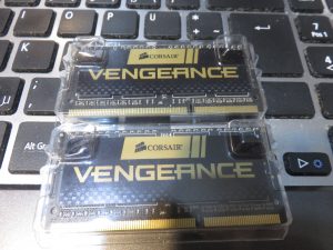
But what i find really disturbing is that we have november 2017 many years since its known. And these are newly bought sodimm modules (brand name in fact from corsair, CMSX16GX3M2B1600C9. Both of the 2 modules alone also are affected.
Un-voluntarily that also leads myself to the question, does anyone know of similar sodimm modules (can be slower i dont care) which do not have this issue? Or a way to increase the ram refresh rate on a notebook where this seems not available in BIOS? (I guess i could go read the chipset datasheets but maybe some tool already exists …)

Filed under: Hardware — Michael @ 18:45

2017-11-05

Genetics history

Maybe a little off topic. But if one looks at DNA sequencing technology, in 2001 sequencing one humans genome cost 100 million USD, in 2015 it was down to slightly above 1000 USD. Today in 2017 you can buy a new DNA sequencer the size of a mobile phone for 1000 USD. Considering this, humankind today basically has the technology to sequence every human genome.
If someone asked me 10 years ago, what one can do about inherited genetic diseases or any thing else genetic. I would have said, wait 200 years till we have molecular-nano-technology and hope WW3 doesn’t happen. But in 2015 Chinese researchers edited human genes in embryos with some success. But still thats basically individual cells in a lab not an adult made of 1013 cells. But in fact similar methods have already been used and demonstrated to also work with individual organs in vivo in adult mice (not sure who did this first or when, but google finds quite a few things). And what i read few days ago according to interim results, non human primates, editing over 20% of liver cells successfully after a single dose and no adverse events with multiple dosing.
Now one wonders a bit, if one extrapolates this, where this tech will be in 5, 10 or 20 years. I think the next decades will be very interesting in this area.

Filed under: Off Topic — Michael @ 00:41

2017-10-07

Samsung CLP-365 Laser printer paper feeder repair

About 3 months ago my cheap/small color laser printer stopped eating. It tried but most of the time it just failed and very soon it completely stopped working, giving a generic paper stuck kind of error so i had to take it apart and fix it as i needed it. I am writing this 3 month after fixing it, as i didnt had time before, but maybe its still useful for someone.
I have the suspicion all printers of this design will fail this way.

Disassembly

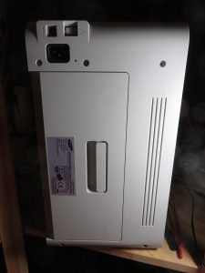
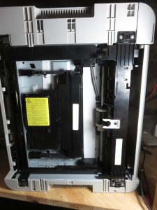
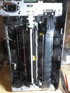
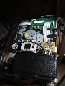
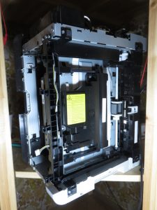
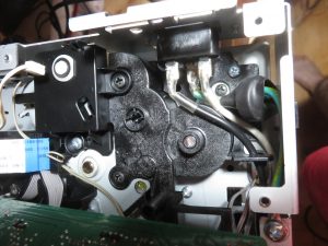
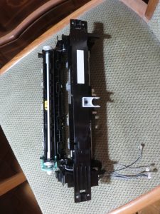
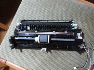
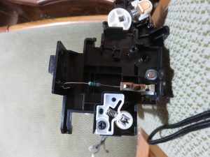
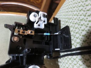
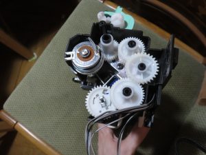
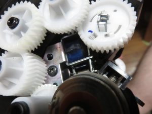
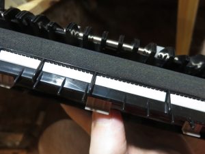
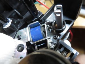
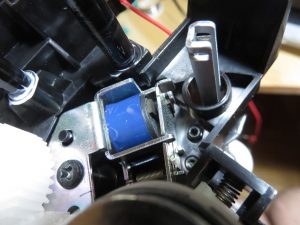
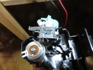
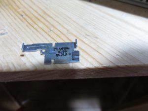
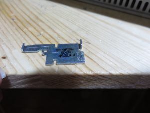
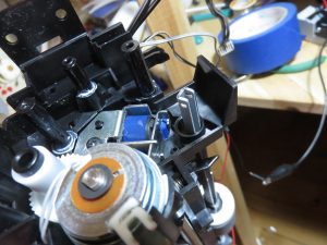
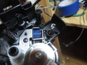
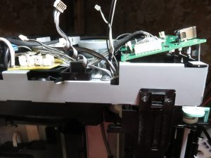
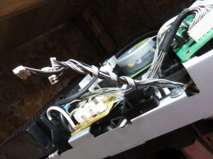
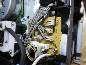
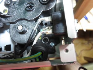
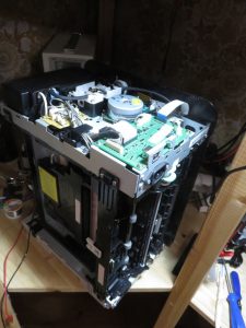
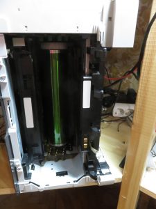
The printer is held together with screws and little plastic hooks, below are some pictures of my disassembly of it. The part we need to get to, is a small steel part which is moved by a solenoid.


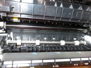
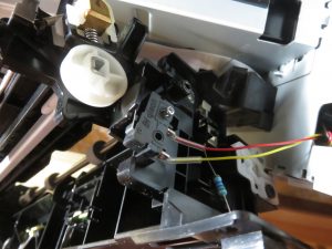
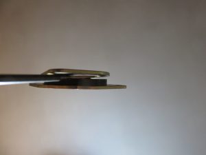
Below is the part that causes the problem, the sticky foam thing on it has become slightly sticky on the wrong side and is also squished. The device still works if the solenoid is pulsed with sufficient power.
Repair

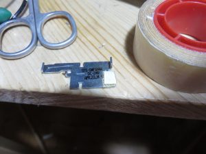
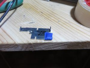
This is very trivial, remove the decaying black foam thingy and replace it with something that is non sticky on one side and
has dimensions somewhat similar to the original. I used very strong double sided tape to get the thickness and covered in chinese “blue” painters tape from my 3d printer to make it non sticky on one side. If you can, test that the solenoid works before reassembly.

Reassembly

Just undo the disassembly in reverse order, weave all the wires back in as they where before.


3 Months since the repair above, my printer still works and had 0 paper feed failures (unless it run out of paper).
Now (2023-12), 6 years later, i am still using this printer and it still works with no further problems :)

Filed under: Hardware — Michael @ 18:12

2017-06-24

Stepper motor vibration damper lifetime

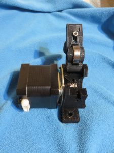
When i installed the vibration dampers a few months ago on my 3D printer. I wondered how long the metal to rubber connection would last. One or 2 days ago my extruder started to skip. After checking it and the hot-end for clogging, i found the vibration damper was no longer in good shape. about 50% of the rubber had separated from the metal.
Thus the lifetime of that one was about 2 months with low to moderate use.

Somewhat expecting this i already had a bag of replacements and replaced it. Lets see if this is a one time failure or if this repeats. Opening the arm of the extruder when not in use should reduce the stress on the part though. But until i see a repetition of this failure mode ill leave things as they are. So as to exclude that this is a one off faulty part.

Low cost 3D printers (in 2017) are “fun”, theres “always” something that needs adjusting or fixing.

Filed under: 3D printer — Michael @ 00:04

2017-04-23

Tevo tarantula and flex filaments

The extruder of the tarantula is capable of printing flexible filaments. But its not good at that.
What worked best with the original extruder was to push the bowden tube up to the gear of the cold-end and to disable retracts.
With that it was possible to print stuff at 15mm/sec with some success. 30mm/sec did not work for me, at that speed the filament found a path of less resistance than the intended. That was with 0.4mm nozzle 0.2mm layer height.
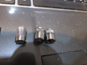
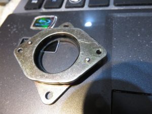
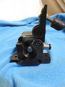
To solve that, the cold-end of the extruder needs to be replaced. Looking at thingiverse i found several printable extruders that looked like they should be better. The one i printed and tried first was the RSE-2 extruder. Which worked a lot better but required hacks to make it fit. It needed a spacer, to not hit the x carriage, required a separate piece of smaller diameter PTFE tubing, M5 coupling instead of the M6 i had from the original extruder and was not really well mountable with the 2 screw based vibration damper i had.
So i modified the RSE-2 extruder to correct all the issues i did run into. Printed it, printed it again with correct settings ;). And replaced it.

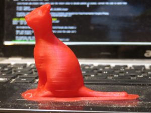
And with that, my tarantula can print flex filament (TPE88 to be precise) at 50mm/sec at 0.2mm layer height, 0.4mm nozzle, Example print:

100mm/sec at 0.1mm layer height with 0.4 nozzle works too but makes not much sense as the higher speed adds too much artifacts and 100mm/sec at 0.2mm is beyond what the hotend of the tarantula can melt, so i did not try that. Also it seems retracts work fine though were disabled in the example shown above, the 100mm/sec test i did had retracts enabled.

The modified RSE2 extruder is available on thingiverse, if you want to print it. It works with MK8 drive gears as well as UM2 Knurled drive gears. The MK8 seems to work better of the 2 in terms of extrusion error per backpressure. and both provide 40-50% more force than the original tevo tarantula one with the same stepper and driver. Some cheap ones from aliexpress:

Filed under: 3D printer — Michael @ 01:28

2017-03-26

Stepper motor vibration damper

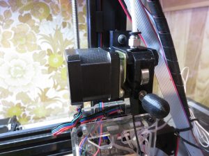
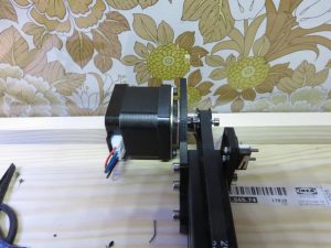
On the quest to improve and tinker with my 3d printer, one area to improve is noise. And a while ago i did buy a set of Stepper motor vibration dampers. The idea is quite obvious, the steppers produce noise and if they are rigidly attached to something solid and big theres alot of area that can radiate the noise. Adding a flexible damper between the source and the rest of the machine reduces the area that can radiate the sound and makes it less noisy.

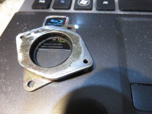
The vibration dampers i got have two raised spots that have no matching holes in the 3d printers parts. They have to be removed or holes be added to where they are attached.

Filing them off by hand is very easy though, the metal seems quite soft.

Ive attached one on the X and one on the Y steppers, these 2 are the most active an noisiest steppers. The Z stepper moves so little that its inaudible except when the printer starts up and runs the auto homing sequence. The extruder stepper too is inaudible except during retracts. I plan to add a damper to it too when i take it apart for some other reason.

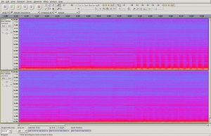
Testing with a microphone inside the enclosure printing a 20mm calibration cube before and after each damper addition

The difference after the 2 added dampers is quite noticeable. The top row is the original and bottom row is with the 2 dampers. The remaining noise is primarily from the hotend cooling fan and less so from the part cooling fan. I plan to replace the later with a noctua fan. The hotend fan is a 30mm fan though and 30mm fans seem rare, i am not sure from where to get a silent quality 30mm fan, noctua does not make one. I could use a 30 to 40mm adapter and different fan duct with a 2nd 40mm noctua fan though, have not decided yet.
Also it seems the addition of the dampers has slightly reduced the waviness of the sides on the printed cube. Its hard to say this definitive though as taking the stepper off and putting it back on changed things like belt tension which may have cause the difference too.

Filed under: 3D printer — Michael @ 20:35

2017-03-05

3D printer

10 years ago, in 2007 3d printer prices broke through the 10000 USD barrier. Today in begin of 2017 you can get a 3d printer express delivered anywhere for less than 200 USD or € from aliexpress and probably ebay too. So obviously i had to get one :) iam not good at resisting “cheap” and cute tech.

The printer i bought was the tevo tarantula which at the time had the most orders in the price range i looked at on aliexpress. I got the version with a large print bed and auto leveling for about 250 €. I almost also got dual extrusion for free as the sloppy seller had a copy and paste error in the offer, sadly she insisted on not including that but she instead added some free replacement nozzles and more free filament.
There were not too many alternative options as i did not want a printer made from primarily acrylic plates (not strong yet brittle and not very hackable). One alternative would have been the flsun 3d i3 printer, my main reason i decided against that was its smaller build area and apparent smaller user base resulting in lack of reviews. I decided against delta style printers simply to keep the number of choices down and with the thought that i might buy a delta style printer at some point in the future.

The tarantula is primarly made of aluminum extrusions with a few acrylic plates. At the time when i bought it, it was shipped with DHL express for free. I was quite surprised about the express shipment and quickly found why, apparently express shipments appear to be subventioned in hong kong. Before receiving the printer i decided to buy a cheap set of random replacement parts for 3d printers, having read of quality issues and having experience with buying things from china ;).

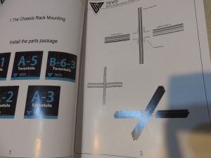
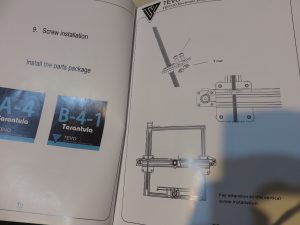
The manual for assembling the printer starts quite good, the first page tells you how to put the base together suggesting to place the horizontal part in the middle, which is not optimal if you want to maximize the print area.

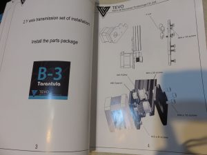
The 2nd page explains how to mount the y stepper motor so that it does not work with the included firmware, it needs to be mounted on the other side or the firmware changed and rebuild, also if you look carefull you will see that on the bottom there are 2 identical acrylic parts depicted, one serving no function and IIUC a left over from a older revission, they do include this part physically, its useless though.

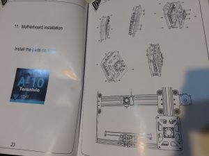
A few pages in, the author apparently decided to stop annotating parts in the middle.

And 2 pages later all annotations are gone, and one has to use trial and error to find out that no included screw fits in some places.

Thanks to the community there are 2 video series on youtube though that explain how to put the printer together. Searching for “tevo tarantula assembly” finds these and might also find future ones. I recommand watching both and reading the manual before and while assembling, that way no mistakes should happen.

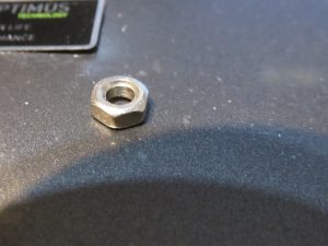
2 nuts included lacked threads entirely, one pulley was bent, the speculatively bought replacement parts included these luckily :)

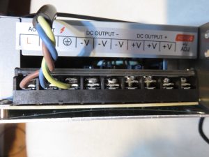
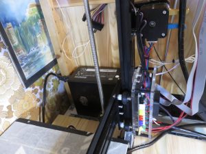
The power supply works fine, sadly theres no real enclosure. The main wire terminals can be touched if the user puts his fingers on the power supply. Theres also no power switch, to switch it off you pull the plug from the wall. The fan of the power supply is quite noisy. Its output is 12V 25A (didnt test if its actually capable of sustained 25A thats just what the sticker says). I quickly replaced it by a random old ATX power supply which i had laying around, that way it has a nearly inaudible fan, no exposed mains voltage parts, a power switch and a few more voltages for free.

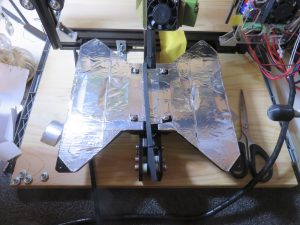
One of the first things i printed was a fan duct for part cooling, that improves print quality. I also covered the acrylic plate below the heated bed with aluminium tape as it appeared to soften from the heat and bend slightly requiring level adjustments between initial power on and when it had heated up. I also screwed the printer onto a piece of wood. That makes it independant of the flatness of the surface its standing on, it makes no difference in print quality though.

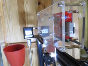
The LCD display as it comes with the printer isnt attached to anything and there seems no really great place to put it wthout extra parts, so i cut and drilled a piece of aluminum and attached it with that on the top. That location works. Slightly lower and in front of the al extrusion it would be in the way of the cables and tube from the print head if it moves higher up.

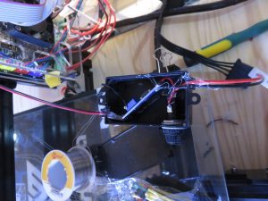
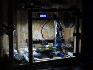
To better see what the printer is doing i added some 12V LED stripe with some kapton tape for isolation and stuck into the top alumiunium extrusion, it exactly fits. Powering this off the 12V line results in flicker as the heater elements being switched on and off cause +-1% voltage fluctuations. I thus stuck a cheap ebay voltage booster in line (12->13v) which fixed this until i powered it off and on, at which point the magic smoke left the voltage booster. Assuming that it didnt like the rather small boost of around 1 volt i took a new booster and this time added a fuse and fuse holder and powered it off the 5v line. After it worked fine over many hours and some aggressive power cycling i put it in a nicer box with ugly hot glue.

Ive also added a glass plate on top of the heated bed taken from a ultra cheap picture frame that was hanging on the wall, temperature cycling it to 130°C and printing a few things on it had no ill effects, no need for borosilicate glass here apparently.

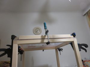
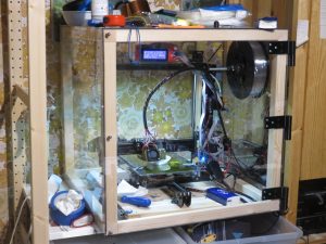
And last ive build an enclosure for the printer out of wood and polycarbonate plates, some screws, silicon and 3d printed barrel hinges from thingyverse. I failed to find hinges in a shop locally that i liked. With these hinges one can also just simply remove the front door by just lifting it up. With the enclosure the print(er) wont get dusty, and is alot less noisy also it appears to have improved the results with ABS.

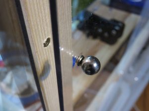
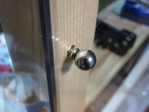
The door locking mechanism is build out of 3 times 2 screws and a ball neodymium magnet, and works very nicely.

Filed under: 3D printer — Michael @ 19:34

2016-12-02

Printing on metal and glass

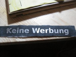
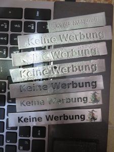
A while ago i had the “need” to make a non removable “no advertisements” “sticker. To do that i tried several different methods to print on and etch metal. The methods where roughly based on various youtube videos for making other things. Its a while ago so i hope i dont misremember the details, i should have written this immedeately…
All the methods start out with a laser printer and then transfer the toner onto the object as a mask for etching.

Cold toner transfer

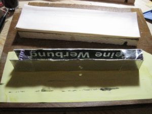
The image to be transferred is printed on normal paper. the object its intended to be transferred to is placed flat on a table and is wetted with a mix of ethanol and acetone something like 8:5 vol. Pure ethanol will do nothing, pure acetone will smear the toner. Then the printout is placed on top avoiding air bubbles and some timespan like 20sec is waited for the toner to soften. Next the printout is firmly pressed by some means (i used 2 pieces of wood and clamps) for some time (i waited 3 min). next the pressure is removed and one waits for it to fully dry. Next it is soaked in water for some time (3min in my case) and then with luck one can peel the paper off while the toner still sticks to the object one wants to transfer it too. Depending on the toner and paper different procedures are likely optimal. Using this to place a mask onto a piece of scrap aluminum worked so-so, some parts of the toner didnt like sticking on my first attempts. Also this method is only suitable for creating a mask for further processing, you would not want to use this to print onto metal as a final step as there is still paper sticking to the toner.

img_4807-small

Hot toner transfer

The image to be transferred is printed on “toner transfer paper” (from ebay). The object to be printed upon is heated to slightly above the melting point of the toner (likely around 100°C) (i used a kitchen hot plate). Its important to get the temperature approximately right, too hot and the paper will be burnt. Also IR thermometers do not work accurately on shiny metal surfaces. The paper is then placed on the hot object and pressed firmly onto it (i used a silicon tube with a glass rod in it rolling over the paper several times). Next the object is taken off the hot plate and let cool. When cool the paper is removed, the toner mostly sticks fine, some individual tiny holes may be present in the transferred toner. To ensure good adhesion i reheated the object to >50°C above the melting point of the toner.

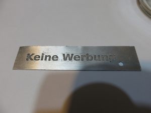
Heres an example of the result of this method using the last piece of scrap aluminum i had laying around:
img_0714-small

Printing multiple times (if you can get the alignment right) or otherwise increasing the toner density improves the results of both methods. Also if there are defects, tiny holes or other you want to paint over them with something before etching. You also can apply some surface treatment like sanding or brushing to the metal before the toner transfer …

Etching

For the aluminum scrap pieces i had i used simple water and table salt as electrolyte, both anode and kathode where aluminum, separated by Plastic clothespins and held together by sticky tape. After several tries i learned that lower currents and voltages seem to work better. that is for the small piece i had something like 1.8V and i think 100mA for 2 hours. (Note, if you attempt to repeat this, you do so at your own risk, Electrolysis of water and table salt produces different things depending on the condition and electrode materials. Other electrolytes may be a better choice even though NaCl seems safe in this setup.)
After etching the toner mask needs to be cleaned off (unless it fell off already which it sometimes did and sometimes it stuck really
well) it can be removed with acetone or with patience also with other random things.

The electrodes with the cut up pieces of a clothespin and tape:
img_4806-small

The results of several attempts
img_0732-smallimg_0666-small

Transfer without etching

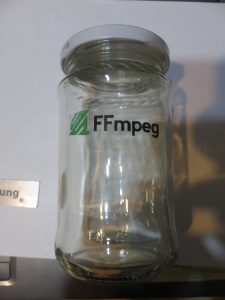
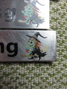
One can of course also skip the etching and keep the “mask” as the final result even with color or even as a addition to a previous etching step. This also works on glass (if you can heat and cool it without it shattering)

The results from my attempts for this:
img_0735-smallimg_0673_small

After this i had no scrap pieces of aluminum left nor really time and the problem i was trying to solve (someone repeatly removing my fathers no advertisement sticker from his mailbox … to collect more free coupons or paper … solved itself as she stopped)

Filed under: FFmpeg,Off Topic — Michael @ 14:37

2016-09-12

Notebook keyboards 2016

A few days ago i replaced my acer notebooks keyboard, several of its keys had become unreliable months ago I first attempted to clean it but that just broke some little plastic part off with no improvement. The process was a bit boing, 24 pages of the (well written) service manual 36 screws some epoxy and 2 hours later my note book was working again with new keyboard.
This notebook is definitely not built to be serviced, having to disassemble it partly from the bottom to get to the top. Some screws screw into plastic, many of them have the plastic cracked after screw removial making reassembly tricky. Some screws screwed into metal inserts, 2 of which broke off without me even touching them, requiring the epoxy to reattach the metal inserts onto the brittle plastic. There are also plastic latches before you disassemble things, the ones of the main door at the bottom are indestructable it seems but the ones deeper inside seem not intended to be reused judging from the smaller number of clicking sounds when reassembling …
My previous acer notebook i once dropped and it still works. It also still has its original keyboard and the hp omnibook i had before i could use until many of the keys on its keyboard had no readable symbols on them anymore. Though today that old hp notebooks plastic parts have also become extreemly brittle but its keyboard could be exchanged by just removing one or 2 screws IIRC.
In the distant past electronics seemed to last forever becoming obsolete long before failing. Now it seems most stuff fails long before becoming obsolete.
img_4802-smallimg_4803-small

Both keyboards after the replacement:
img_0676-small
And most disappointingly no parts where left unused after reassembly nor where any missing. I guess my workspace was too tidy.

Filed under: Hardware — Michael @ 22:10

2016-07-04

voltage tester

DMMs are usefull but for some things they are a bit inconvenient and bulky. So for fun and less so for potential usefulness i bought the 8 in 1 voltage tester depicted below, smaller than a DMM, puts a small decreasing load on the tested circuit allowing things like GFCI testing and so on.
IMG_4760-small
But when testing at 220V AC it produced:
IMG_4764-small
In fact the 380V LED lights up down to 175V.
Opening the thing up without destroying it proofed to be some effort, the inside:
IMG_4765-small
I was already starting to trace things and draw a crude schematic to debug this when i noticed:
IMG_4769-small
A unpopulated component, for a fraction of a second i considered a optional features quickly discarding that in favor of the hypothesis of excellent quality management in this ultra high end (it cost almost 5 euro) tool.
So after a bit of thinking, guessing and testing i wanted to solder a 100k resistor in there but my 10-15 euro variable power soldering iron didnt work anymore. That one was even from a local shop not ebay. Luckily i still had my grandfathers soldering iron:
IMG_4771-small
Which after exchanging the tip worked perfect:
IMG_4772-small
and after that all voltages work fine, including 220v:
IMG_4773-small
PS: Recommendations for a good and cheap variable power soldering iron are welcome! ;)

Filed under: Electronics — Michael @ 03:45
« Previous PageNext Page »

Powered by WordPress