Lair Of The Multimedia Guru

2018-11-04

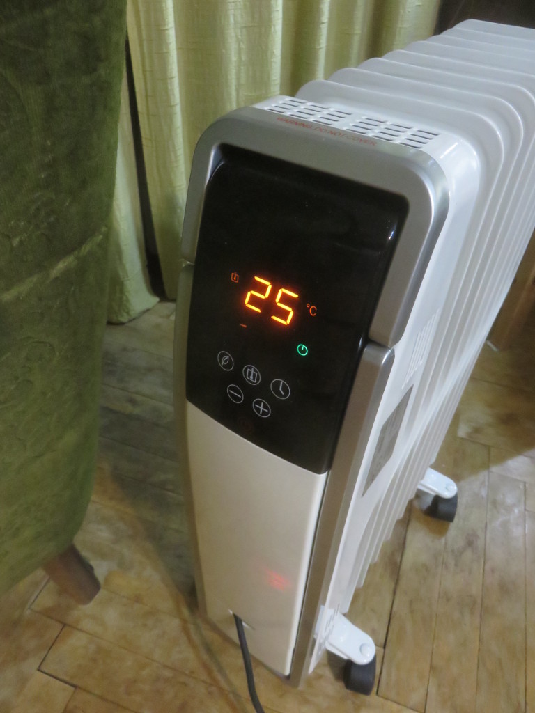
Silencing an oil-filled radiator

The way oil radiators work is that the oil inside is heated by electricity flowing through some resistive heating element. The heated up oil then raises due to lower density and that way circulates in the radiator which then gets hot and heats the air.
Noise is produced by either mechanical thermostats or relays, so every time the set temperature is exceeded by some fixed amount some mechanical switch or relay switches which makes a click. That can be annoying if one tries to use a device like this in an otherwise silent bed room.
The Device:

To get it open one has to remove 2 screws and slide teh front down:

The top can be removed too after that and after removing the handle.

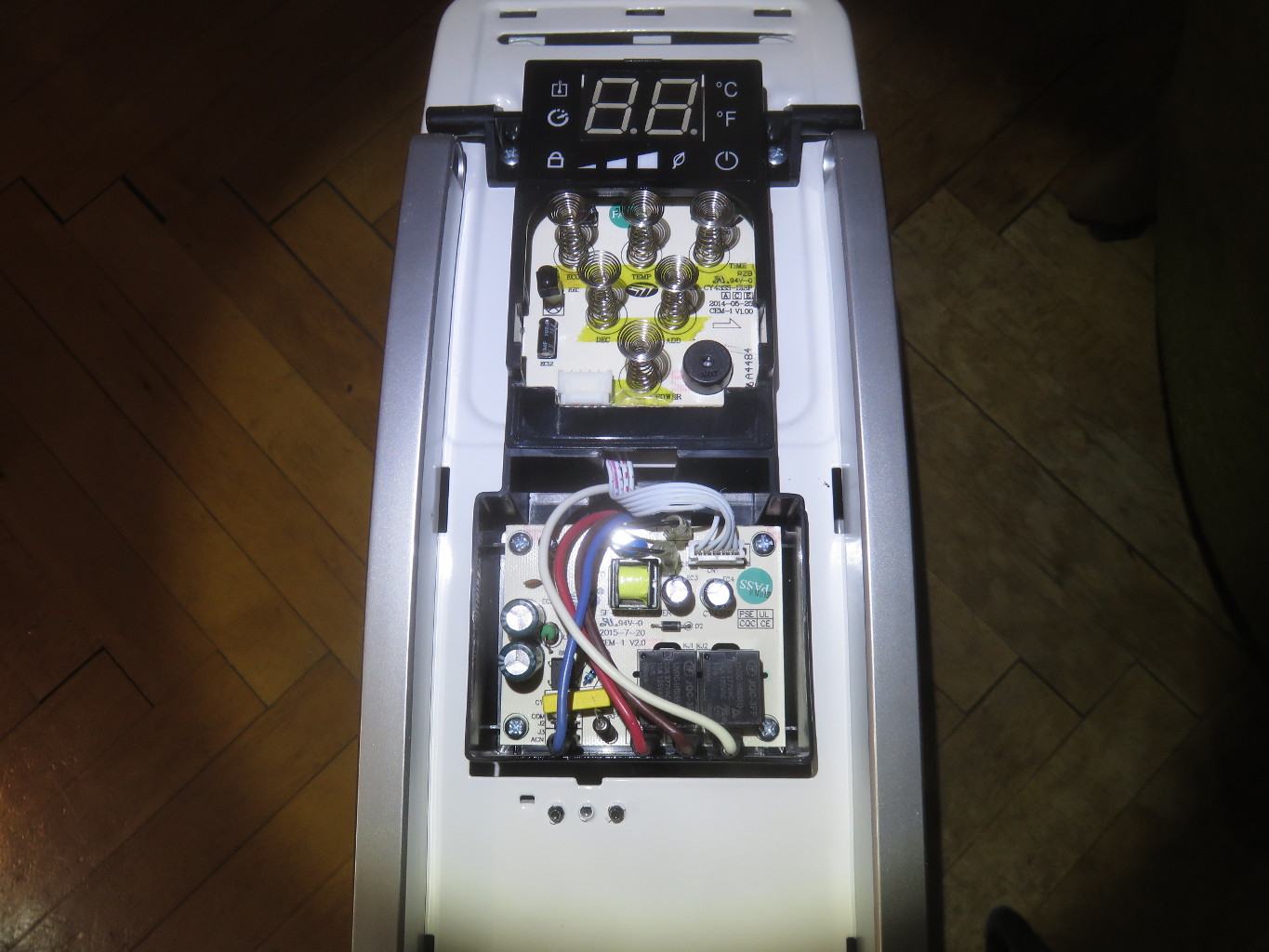
Three more screws later the next front layer can be taken off, that is as much as we need to disassemble to access all parts we need to access:

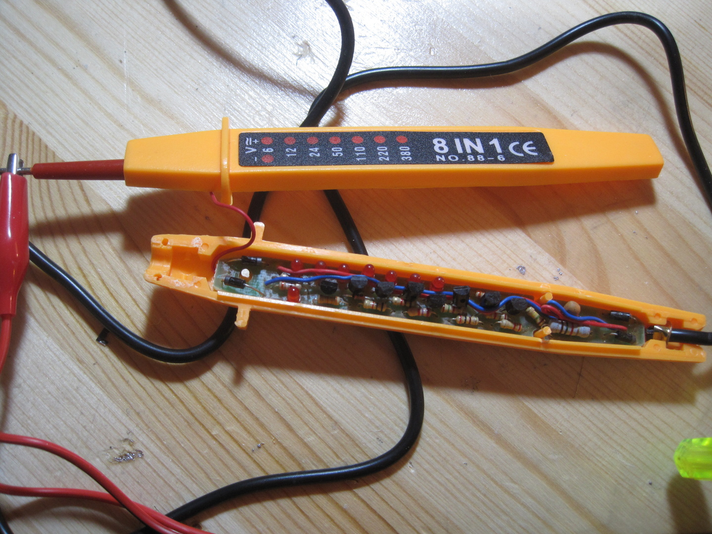
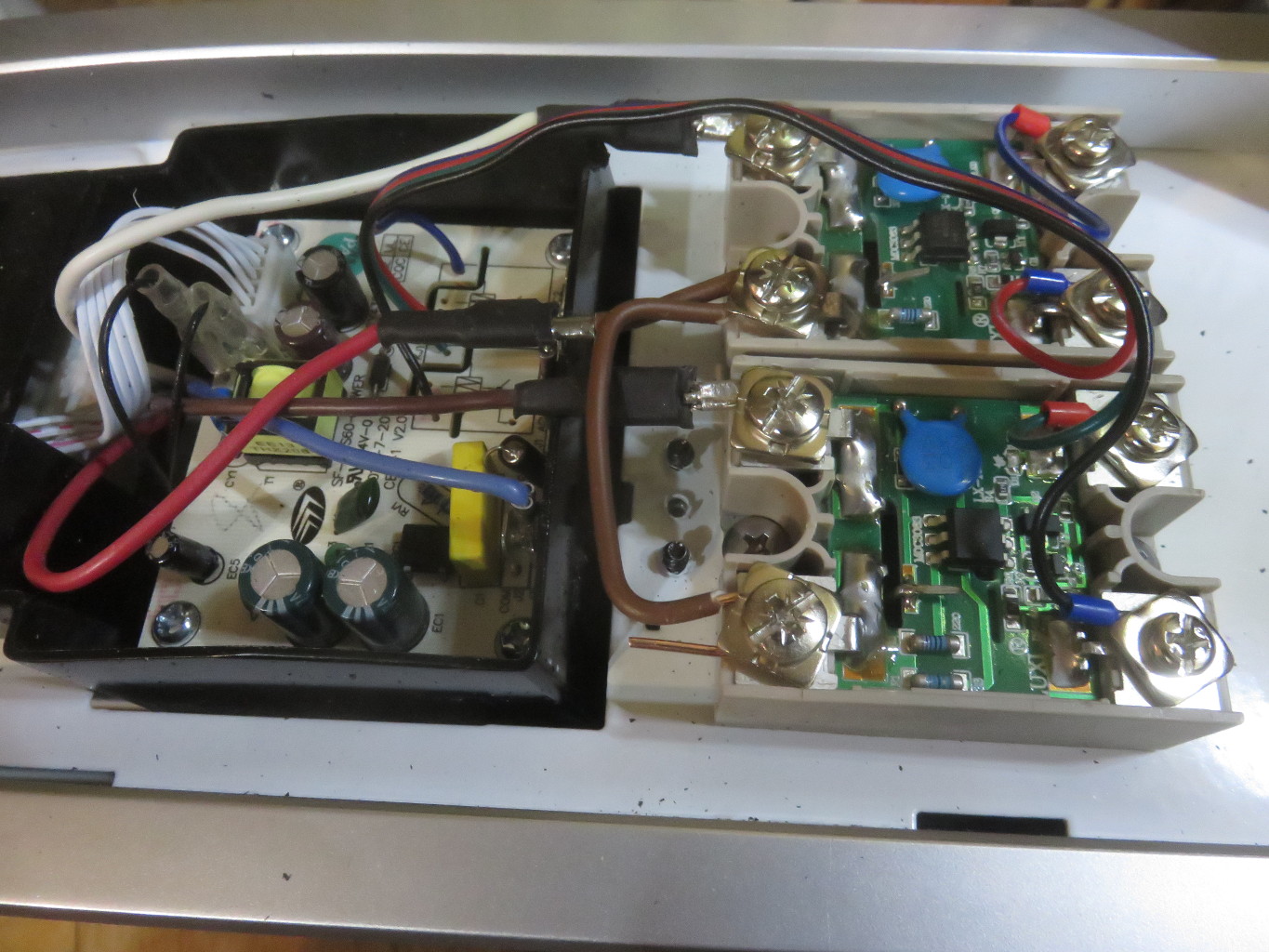
Removing the lower board is trivial, just remove screws and disconnect cables:

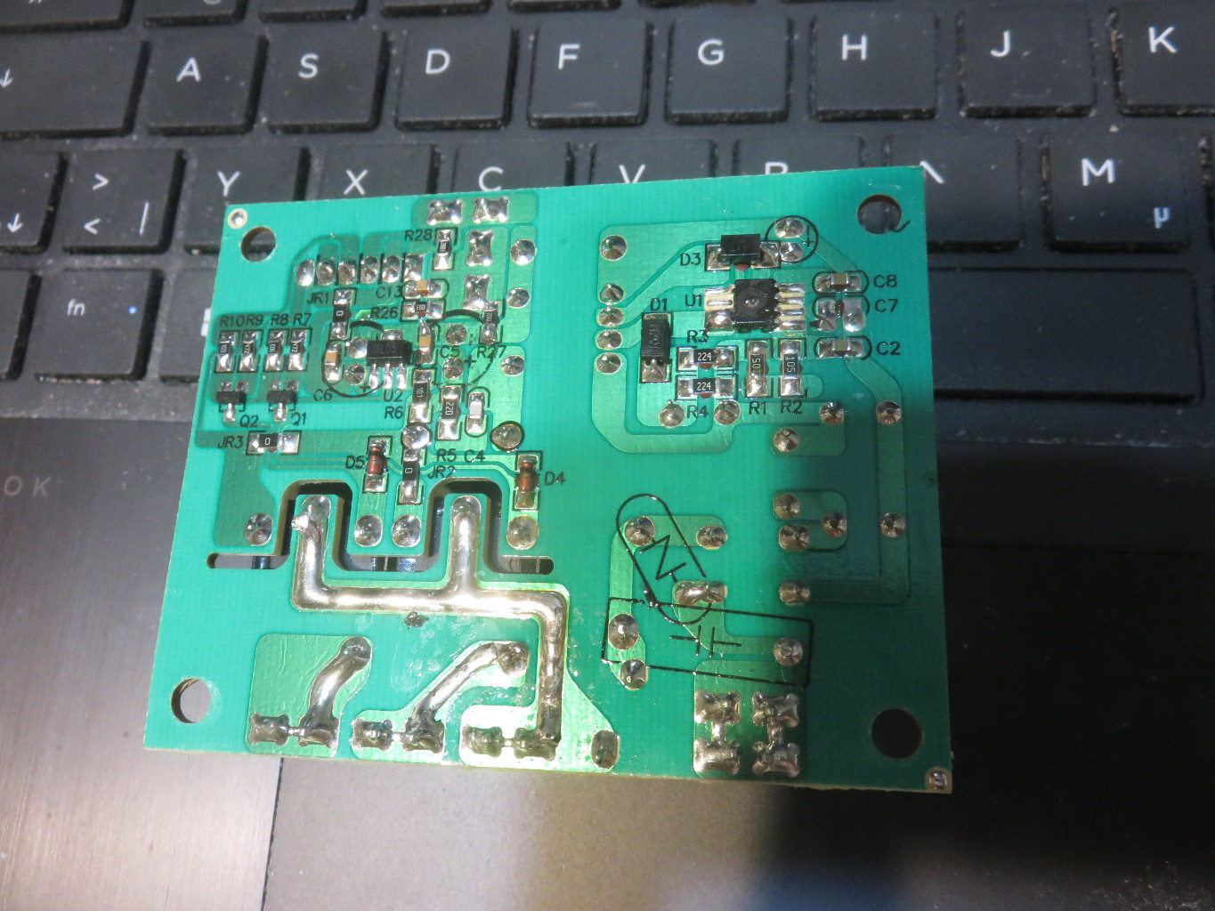
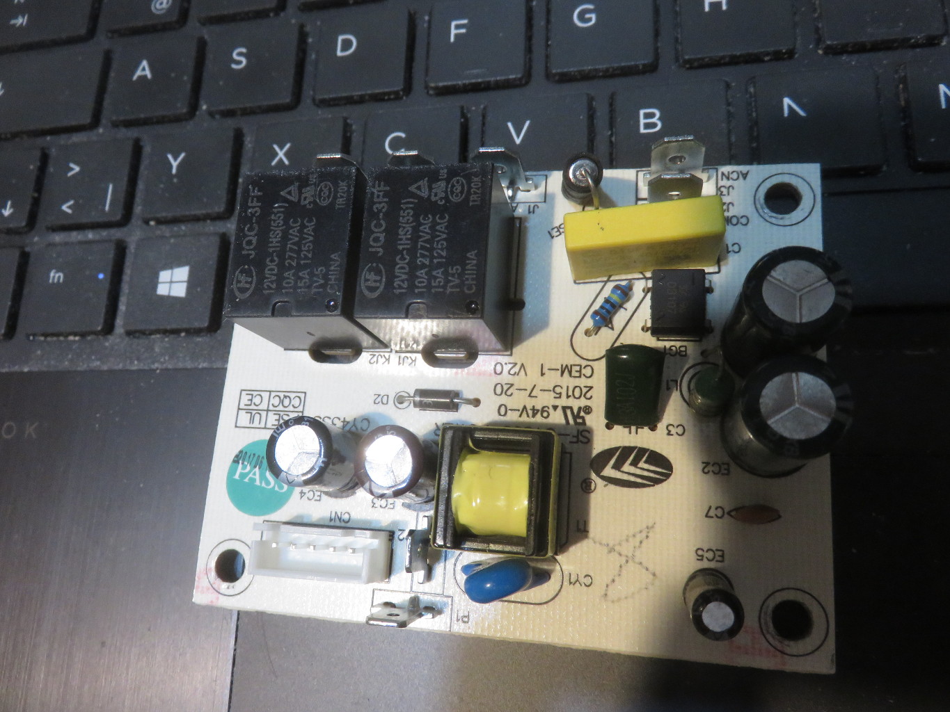
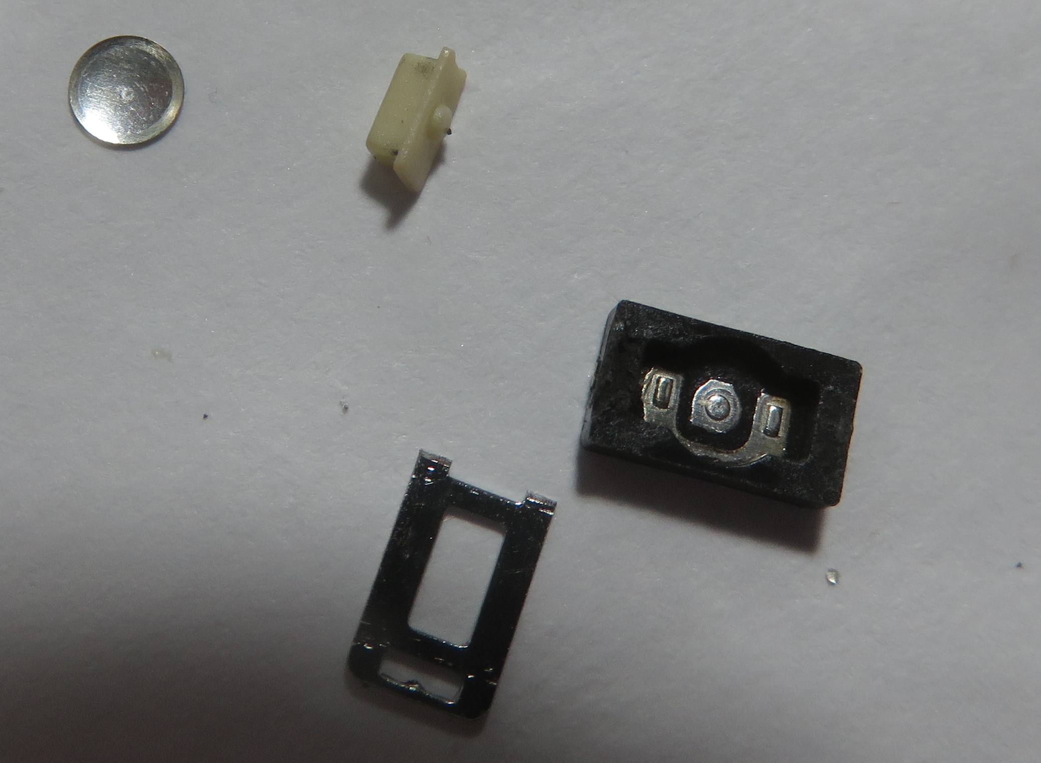
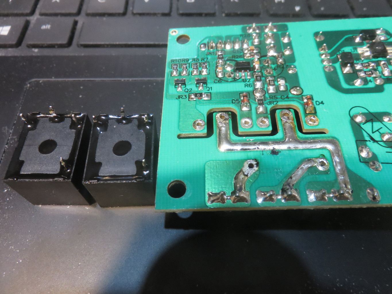
Next the 2 noisy relays are desoldered:

To replace the relays 2 solid state relays from ali express are added, they are rated at several times the needed current (i expected the rating to be exaggerated when i ordered and wanted to make sure they arent underrated but it seems the seller actually was honest with the rating). Careful attention is also paid to their heat-sinking requirement (which is none at the currents they would be used with).

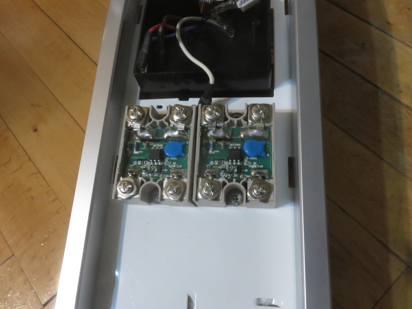
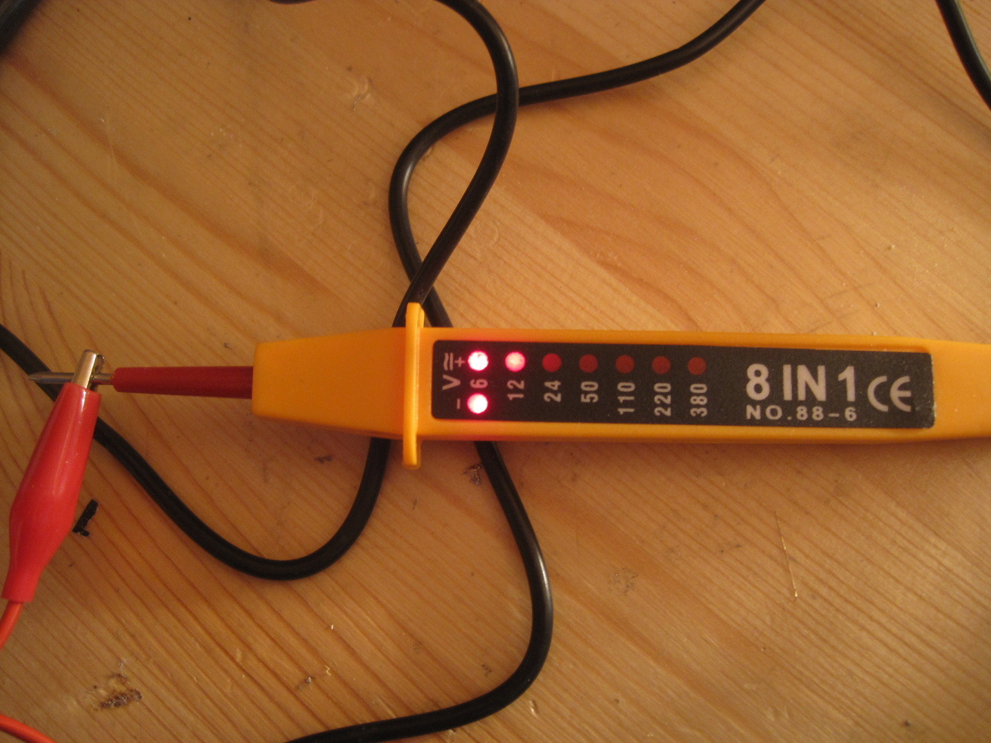
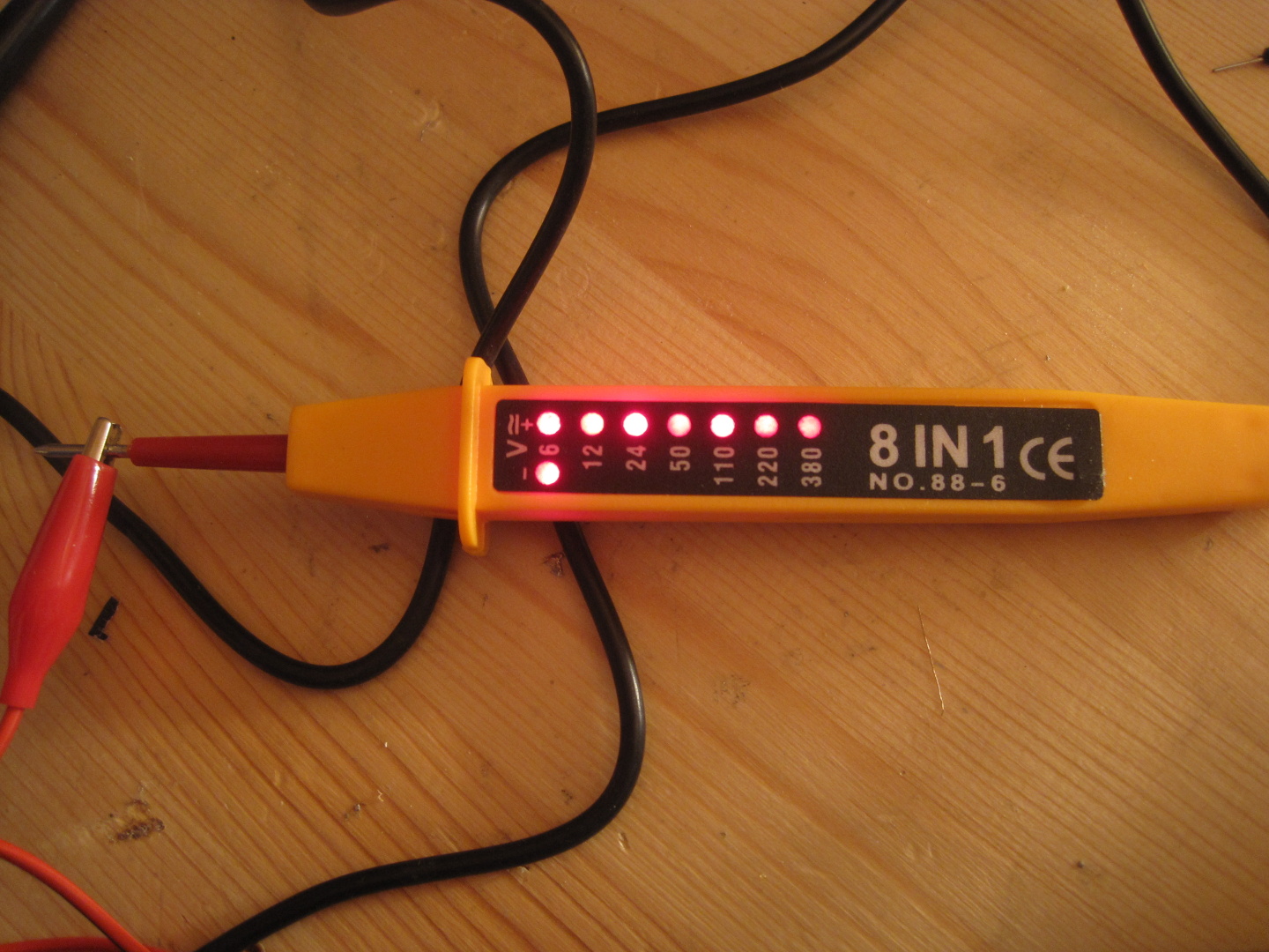
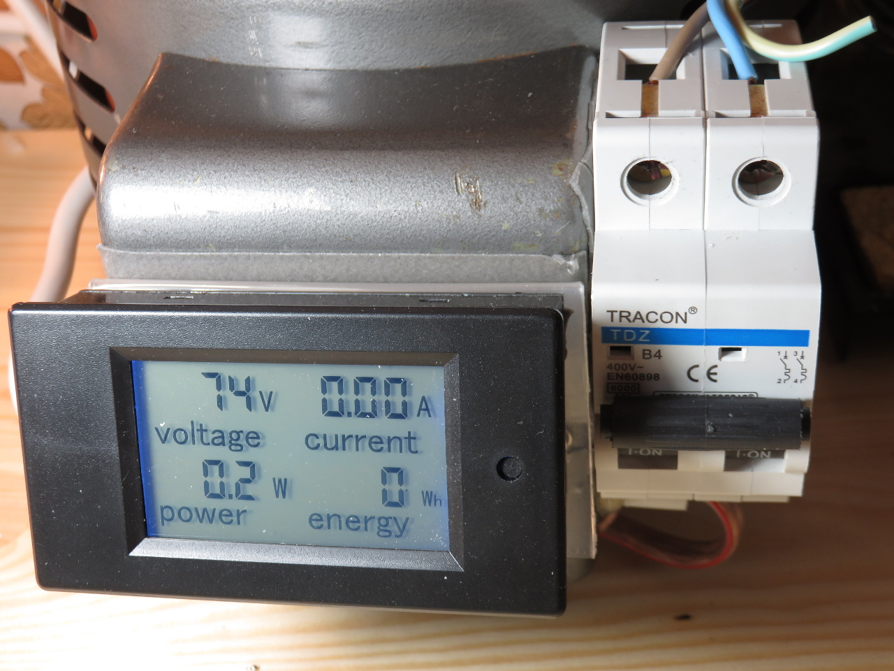
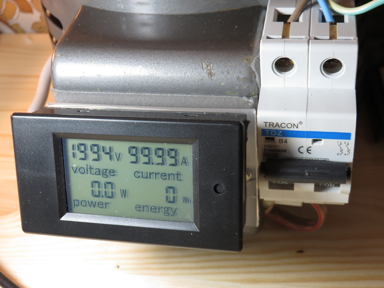
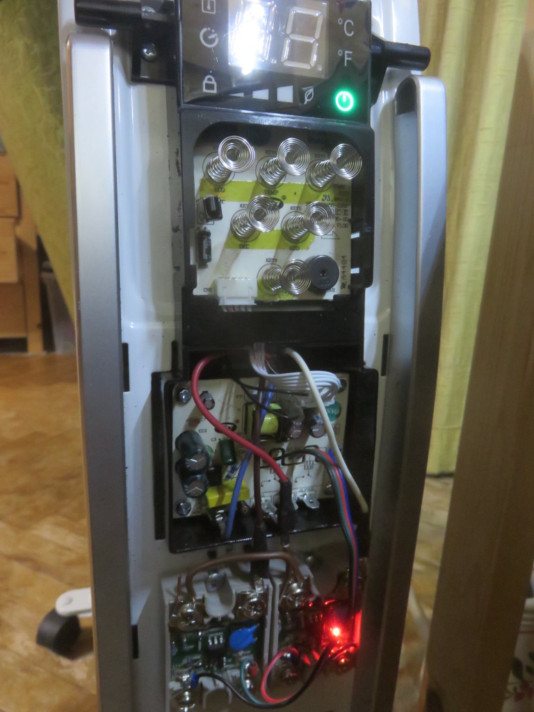
And a quick tests shows they are working fine and also have a pretty red led indicating that they are on:
btw, they are lacking their top cover because the heater could not be closed with it on, and it serves no purpose in this case

And now i have a silent electric oil heater radiator thing … click …WTF
Was there some part expanding from the heat and making a noise ? something on the 2nd board i didnt look at ?
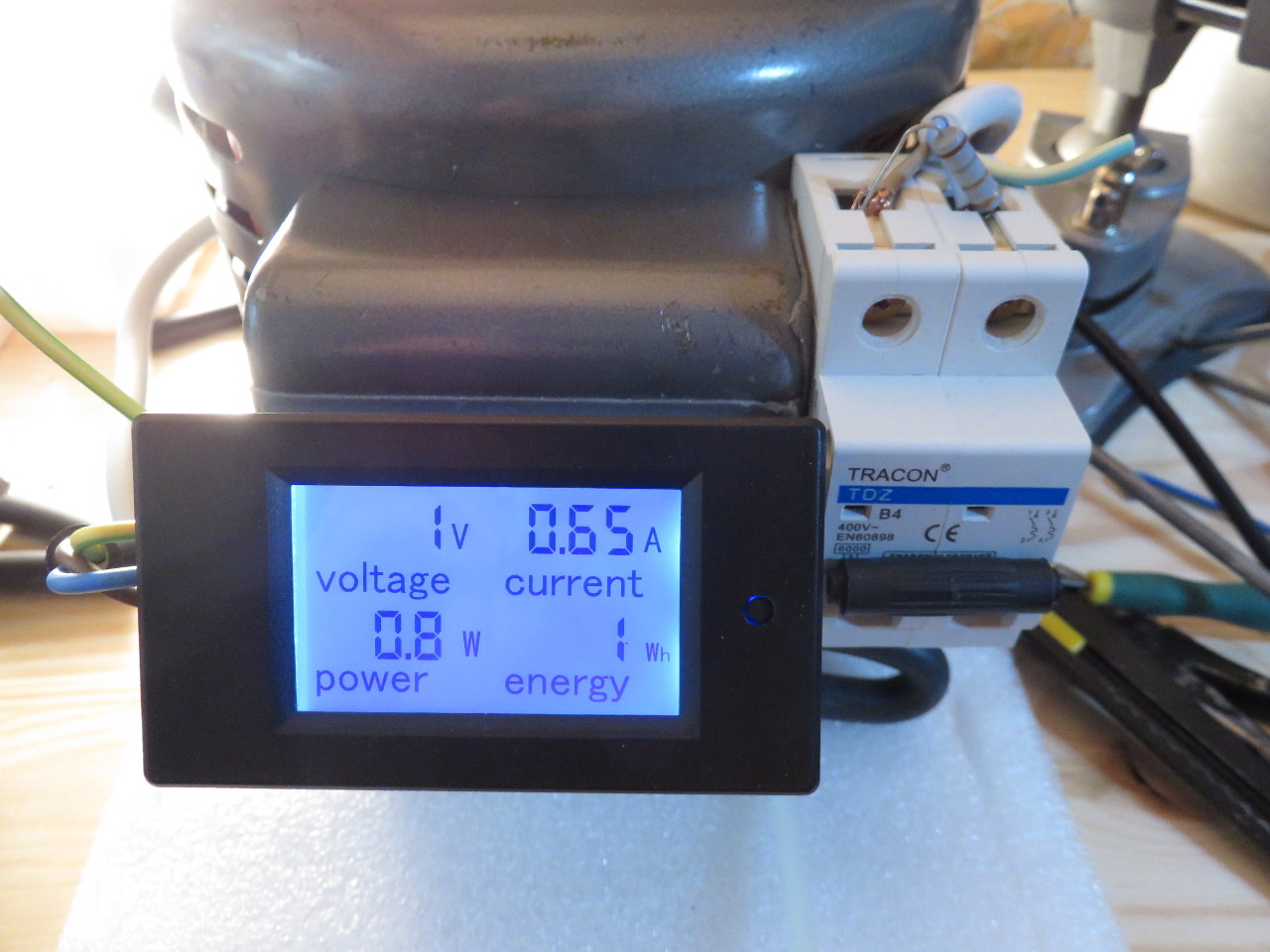
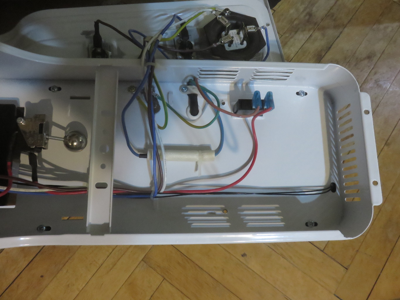
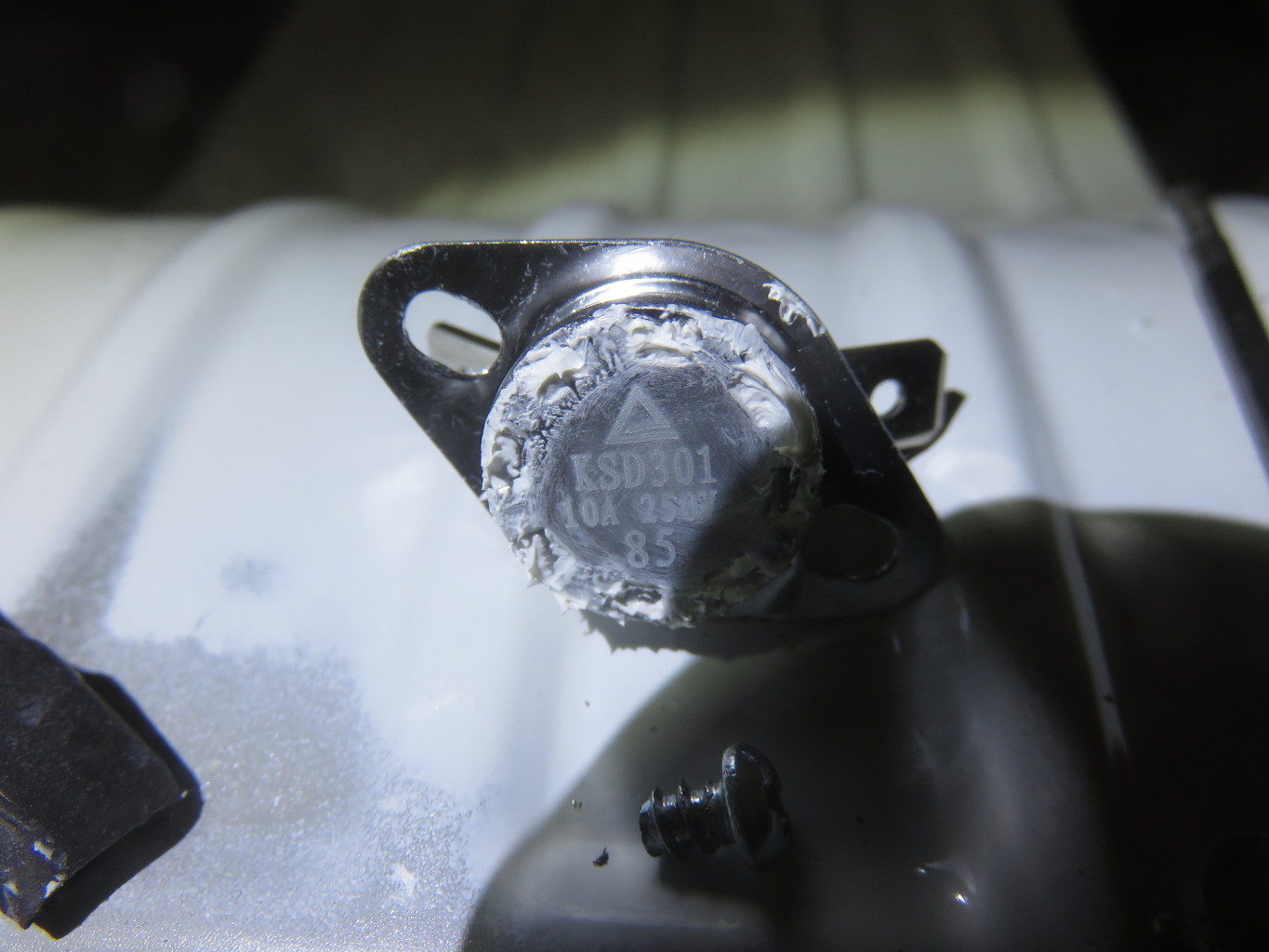
I had it already reassembled and had to disassemble it again to trace where that came from. The radiator is rated for 2000W, one circuit 700 W or so and the other the rest to get to 2000W. It contains a fixed mechanical thermostat that disables both heating elements in case of overheat. and the 1300W heater has its own mechanical thermostat which disables just it at 85°C. The surprising thing here (to me) was that 85°C is easily exceeded by the 700W element alone. So the heater rating of 2000W is misleading at best because the heater under normal conditions will only heat with the 700W element continuously. The 2000W will just be used for a short period. After learning about that ive checked the shop where it was bought long ago and looking at heaters rated at 700W (which they have too and which are smaller) one quickly finds customer complaints that the 700W units switch off and are unable to sustain heating at 700W. This is Europa not China :( I did not expect to find this …
Ok back to the silencing, the solution here is in fact very simple. As the 2000W and 1300W modes are fake and only sustain 700W anyway and i have to assume for a good reason. The solution is to simply disable the 1300W part.

With that change the radiator is now actually silent and also looks cooler with the relay led shining through the front. Looking at the images i regret a bit that i hadnt thought about replacing the front by a transparent polycarbonate window. it would have looked cooler ;)

Filed under: Electronics,Off Topic — Michael @ 23:04

2018-09-20

Testing high voltages

The chinese negative ion generator i used in 3d-printer-particles-air-pollution made me a bit curious about what voltage it outputs. The page from the seller mentions several different values, 2-5kv, 5-8kv, 5kv and other things. So one wonders what it actually is. This sadly cannot be directly tested by just using a normal DMM as its a bit outside the supported voltage range of the average DMM. High voltage probes for DMMs exist but even chinese ones seem to cost at least ~70€ and i wouldn’t trust them safety wise. So lets make one for 1€ which we can trust to be unsafe.
We start out with a inappropriate high voltage probe enclosure, which we disassemble and remove the unneeded parts:

The innards of our HV probe is simply a 90MΩ resistor, which will together with the internal 10MΩ resistance of the DMM form a 10:1 voltage divider, extending its input range.

Lets try:

1470V, hmm
Checking what output saftey resistance this device uses:

It seems its something around 20MΩ, maybe 2 10MΩ resistors ? Its potted so no easy way to tell exactly. But this changes our output voltage estimate as now our probe effectively is 110MΩ instead of 90MΩ. That raises it to 1764V, but it still feels a bit lowish to me. Also the 120MΩ to ground would draw 15uA, which could pull the voltage down by an unknown amount. This ionizer thing after all is not intended for producing any current.
To test for this we can use a higher value resistor. I do have a 1GΩ resistor (though it cost more than 1€), with it we get:

Aha, 4270V, so the 15uA does in deed quite significantly pull the voltage down. Now with 1GΩ we still pull 4uA here so this is likely still a too low estimate. Sadly i do not have a higher value resistor ATM.
What remains is to check that the 2 HV probe setups actually work at all, we must test this as we cannot be sure the DMM behaves as expected in this setup.

Both produce expected values at a 1kV test input, the voltage appears to be slightly below 1kV though.

at a 500V test input the value matches much better indicating that indeed the 1kV test output seems lowish

disclaimer: high voltage is dangerous, do not play with it or replicate anything described above. If you do anyway you do so at your own risk.

Filed under: Electronics,Off Topic — Michael @ 10:39

2018-09-09

3D printer particles / air pollution part2

When i experimented with measuring the amount of particles from my 3d printer, i noticed the majority originated from when the heat-bed was turned on. I had cleaned the inside of the printer roughly before, so this was slightly odd. More investigation shortly later revealed the cause though.


The use of tinned multi-core wire without ferrules. Why it was done this way you may ask? Because between the incomplete and poor official documentation, the consumer made videos of how to assemble it and my plain lack of knowledge about how multi-core wire with and without solder behaves in this case. This way of connecting the wires seemed sound enough and there also where no ferrules included with the printer kit.
That said if you did connect high current wires in a similar fashion, you probably want to consider redoing it with ferrules or in another reliable way, like directly soldering to the board or soldering a solid core wire onto the multi-core as an intermediate. Also keep in mind iam a programmer not a expert for this so do your own research if failure of a connection could have some real consequences.
My printer is fine, the heat-bed also didn’t behave erratically or anything. And i never trust/trusted it anyway in terms of safety to ever run it without someone being at home, so in my case it was impossible for this to cause any real harm. But i still didn’t expect that …

I didn’t had any fitting ferrules, so the way i fixed it was to take some terminal connector thingies, which when one cuts half of each off are basically ferrules. I also didn’t had a new terminal block that was rated for enough amps to replace the roasted one. I will properly replace these once i have proper replacement and have time. Quite likely next time that printer needs some kind of “service”.

Filed under: 3D printer,Electronics — Michael @ 17:09

2018-07-14

Chinese worklight repair

A while ago i bought a quite cheap flashlight/”worklight” from aliexpress. Not the best quality but it worked.

About 3 days later its button started to work only intermittently. A few days later it basically didnt work anymore.
I wonder why these items have so many 5 star reviews.
Yesterday after putting some food in the oven in the morning i had some time while waiting for it.
After disassembly, it looks like this:

The button is a standard SMD button, i had some equivalent replacement.

After exchanging it, it works again. Lets see for how long …

Almost forgot, the failed button after gentle disassembly:

Filed under: Electronics,Off Topic — Michael @ 22:14

2016-07-04

voltage tester

DMMs are usefull but for some things they are a bit inconvenient and bulky. So for fun and less so for potential usefulness i bought the 8 in 1 voltage tester depicted below, smaller than a DMM, puts a small decreasing load on the tested circuit allowing things like GFCI testing and so on.
IMG_4760-small
But when testing at 220V AC it produced:
IMG_4764-small
In fact the 380V LED lights up down to 175V.
Opening the thing up without destroying it proofed to be some effort, the inside:
IMG_4765-small
I was already starting to trace things and draw a crude schematic to debug this when i noticed:
IMG_4769-small
A unpopulated component, for a fraction of a second i considered a optional features quickly discarding that in favor of the hypothesis of excellent quality management in this ultra high end (it cost almost 5 euro) tool.
So after a bit of thinking, guessing and testing i wanted to solder a 100k resistor in there but my 10-15 euro variable power soldering iron didnt work anymore. That one was even from a local shop not ebay. Luckily i still had my grandfathers soldering iron:
IMG_4771-small
Which after exchanging the tip worked perfect:
IMG_4772-small
and after that all voltages work fine, including 220v:
IMG_4773-small
PS: Recommendations for a good and cheap variable power soldering iron are welcome! ;)

Filed under: Electronics — Michael @ 03:45

2016-01-11

Thermoelectric cooler

A while ago searching around on ebay for geeky/nerdy toys i found some Thermoelectric coolers/peltiers for around 2$ with free shipping. So i bought a few of them …
IMG_0474-small

They all worked fine, one had a hole in its silicon sealant though which ive “fixed” with hot glue (first heated the element up to reduce moisture inside then re-sealed it), i dont remember why i didnt use silicon …

I experimented a bit around with 1 and 2 stage TECs on a old heat-sink + fan that was laying around, the best combination interestingly was 2 stages first at 12V 2nd at 5V. though the gain for 2 stages over 1 stage was disappointingly small, IIRC a little over 10°C. Its also interesting to note that my chinese IR thermometer was not able to measure the temperature of the frosted top, it displayed way too low values. Actual real lowest value achieved was measured with a Type K thermocouple, frozen onto the TEC in a drop of water and frosted over for a while (the snowy stuff that forms should provides some extra isolation).
IMG_0377-small
The 2 TECs in above are attached with cable ties, which was very limiting in what could be placed on top

For some reason yesterday i decided to test using the TECs for heating instead of cooling by reversing the input polarity.
That indeed worked and the same device happily boiled drops of water. I didnt think too deep about what the maximum temperature for the TECs was, i didnt expect failure below 180°C, but the top element died at probably around 120-130°C (K type thermocouple in drop of oil on top).
Not entirely believing the apparent facts, i picked another unused separate TEC1-12706 and retried, heating it to 160°C
which seems to have done no harm to it. Though i used the IR thermometer for measuring the 160°C, i should retry this probably with both thermometers but then according to the ebay article page they are max 70°C ;)

Breaking my TEC cooler toy i took it and the failed TEC element apart, Its failure mode was that it showed >10megohm resistance. Cutting its sealant away, it looked like this:
IMG_0460-1280 IMG_0461-1280

And separating it further with a tiny bit of heat and force (probably only heat was needed)
IMG_0463-1280

Also interestingly none of the remaining individual elements tested open, they all had low resistance. I know nothing about TEC failure modes but i wonder if one little part had just cracked from the heat and maybe mechanical stress. They are all in series so one cracking the wrong way should show similar symptoms …

To rebuild the TEC2-toy now ver2, i placed a piece of aluminum on top and tried to attach it with cable ties, but this proofed frustratingly unstable
IMG_0464-1280

My next idea of fixing it with screws, bolts, nuts or such wasnt an option as i lacked parts of sufficient length with non ridiculous diameter. So i cut 2 pieces of the same aluminum stuff and fixed it with 4 springs created out of a single larger spring separated by some foamy stuff for isolation:
IMG_0465-1280 IMG_0468-1280 IMG_0467-1280

In action:
IMG_0470-1280

Also i tested cooling and heating of a glass container with a liquid. (for cooling a drop of water was used as thermal component between glass and aluminum for heating a drop of minnaral oil). Without isolation, the temperature fell to +9.5°C in 1 hour and with some isolation to prevent the warm air from the fan hitting the container, to +2°C in another hour. Iam quite sure sub zero is achievable with a real attempt to prevent coolness loss but i kind of lost patience.
on the hot side i achieved 67°C with the TEC itself being at around 100°C, so if one would risk damaging the unit it might be possible to boil water in a container with it.

Filed under: Electronics,Hardware,Off Topic — Michael @ 05:00

2015-12-25

Bluetooth tracking devices/tags/”key” finders battery lifetime

6 weeks ago (11th november) i switched both the tags i have on and put them in the same drawer in my kitchen, i then tried to connect to them when i remembered about it and tried to make them beep remotely. the itag failed to connect the next day but worked again after removing the battery for a moment, the day after that it failed again and no longer recovered after removing the battery (which was at 2.897V but apparently could not supply enough current anymore for the tag to power up), on last connection it showed 100% battery. Powering the itag off a bench power supply showed that it still worked fine.
Meassuring its current draw, shows 3uA when switched off, and around 1.1mA when on, considering that the tag has to be on to be of any use, that renders it useless as it eats batteries too quick.
the smart finder / “small lovely” continued working till when i tried it yesterday when a connection was no longer successfull, pushing its button it still produced a silent click which on repeated presses got weaker. so it too used up its battery after about 4-6weeks (i had last tried it 2 weeks ago when its battery was shown at 100% in bluthooths stuff).
Meassuring its current consumption, it draws 2.4uA when off, and when on after some initial higher draw fluctuates between 2.7uA and around 88 uA with an apparent average of 39uA.
Note, the current draws depend significantly on the voltage for the itag at least (i tested at about 3V), also the uA meassurements where at the edge of what my multimeter could show so they should all be considered approximate.

In summary, the itag i got eats its battery in 2 days, the smart finder thingy in about 4-6 weeks. I would have tested more tags but these where the only 2 i received. another one i ordered off ebay was lost in shipping apparently

Filed under: Electronics,Off Topic — Michael @ 23:20

2015-11-27

Modifying a 80-250V AC Volt/Amp/Power meter to make it work for 0-250V AC

A while ago i bought an old variac on ebay, it was in good shape but lacked any meter, originally that model had a analog voltmeter or something. That was missing, some cut wires sticking out of where it was. As i got it it also had a 6.5Amp fuse in a fuse holder marked as 4A and its output wires connected straight bypassing the fuse.
When i bought it my plan was to stick a cheap digital meter to it, which is what i did and also a modern and correct “fuse”.
IMG_0395-1280
The meter i found and got supported 80-250VAC, i failed to find one supporting AC voltages down to 0V. I originally had not planed to modify it, as it didnt seem a big issue, but it was just annoying that around 70V it dropped out and displayed junk and then went dark.
IMG_0397-1280
Inside it looks like this:
IMG_0398-1280IMG_0399-1280
I saw 2 obvious ways to make this work with lower voltages, first is to make its AC->5vdc supply work with a wider range of AC voltages, the other is to split the voltage sensing off the supply. As my variac provides around 250VAC in addition to the variable and isolated output, using that seemed to be the easier solution.
But before i continue, a warning, do NOT try this unless you understand what you are doing, mains voltage can be dangerous and can injure or kill. Also not all similar looking such meters are neccessary identical and this modification might result in undefined behaviour in that case.
The voltage is sensed through R3 which is 1Mohm, removing it:
IMG_0400-1280
Results in a working amp meter with 0V:
IMG_0401-1280
Next we need an additional connector for the separate AC power and AC sense input, to get that we just need to clear 2 from solder and cut the 2 connected pins on the other side using a file. Note, if you try this modification double check that the new freed up pin is not connected to anything else by some tracks below, it wasnt in the meter i had but that doesnt imply its not in yours.
IMG_0403-1280
Now its tempting to use the same or a new 1meg ohm resistor for the new sense wire added below (and i did and it worked) but this is probably not safe, first you should clear the conductive parts of the logo which are below, off the board and use 2 resistors in series as there is about 230VAC over it, yes it was already before any modifications but still.
IMG_0405-1280
IMG_0416-1280
You can also slightly adjust the value of this resistor to adjust/finetune the volt-meter.
The other side of the resistor is connected with a mod wire to the newly freed up pin on the other side. Again using a file to make some cut in the board to nicely route the wire around.
IMG_0408-1280
The new connector is then connected like this:

  1. Variac secondary tap 1
  2. Variac secondary tap 2 and Load/Output connection A
  3. Variac secondary tap 3
  4. Load/Output connection B

Testing, works:
IMG_0412-1280

Filed under: Electronics,Hardware,Off Topic — Michael @ 00:11

2015-11-09

Bluetooth tracking devices/tags/”key” finders

A while ago in coverity while fixing FFmpeg bugs there was a some kind of Nominate a bug, win a prize thing, i didnt ever nominate one but this was when i learned about the existence of tile which would have been the prize one could win. A BLE device that can be attached to something valuable and that can then be searched and found with a recent android or iPhone, or the other way around using the device to find your phone.
This seemed potentially useful to me, though i personally have never lost my keys or phone for more than a few seconds, i know someone who does have that problem. So i thought buy a tile or 2 they might come in handy for something but then i saw the price, non replaceable, non rechargable battery and thought ok, didnt expect someone would be that lame. I guess one should not expect any company not to attempt to rip its customers off to the maximum extend possible.

Lucky there are many similar devices, so the goal was to find the cheapest that works and is not just tied to a ridiculous business model. So i bought some of the cheapest i could find (they of course all have user replaceable batteries …)
First is something that identifies itself as

ITAG

IMG_0383-1280IMG_0384-1280
The above one is one example of these, they come in many different shapes, cost less than 5$ with free shipping. The first i got had a different shape and came with a dead battery and also ate a new battery within a day. The second i got is the one pictured above, which worked more or less.
When Off, A long press on its large surface switches it on with 2 beeps.
When On or connected a long press switches it off with a long beep (this renders it useless as its easy to press by mistake)
When on but not connected its led also continuously blinks, draining the battery but making finding easier, it also at least once hanged and required the battery to be disconnected for a moment to function again.
On the BT protocol side setting immedeate alert to 2 results in 30 beeps and led blinks, setting link loss to 0 or 2 has no effect, the device always beeps on unintentional connection losses as far as i could figure out. pressing the button results in a notify with value 0x01 on 0000ffe0-0000-1000-8000-00805f9b34fb / 0000ffe1-0000-1000-8000-00805f9b34fb.
To make the itag only blink and not beep on immedeate alert, 0000fff0-0000-1000-8000-00805f9b34fb/0000fff1-0000-1000-8000-00805f9b34fb can be set to 0x00, this is remembered over disconnects but not over switching the tag off. All other values seem to cause blinking and beeping.
To identify it this may be helpfull:

  • 0x2A29: CEVA
  • 0x2A24: BT 4.0
  • 0x2A25: 12x07x2012
  • 0x2A27: SM-1
  • 0x2A50: Bluetooth SIG Company: Ceva, Inc. (formerly Parthus Technologies, Inc.)
    Product Id:13330
    Product Version: 26369

Smart Finder

IMG_0380-1280IMG_0386-1280
The above is another sub 5$ tag, which appears identical (minus the logos) to tags on amazon from chirotronix and ikee.
The official software for android (“small lovely”) has a rather long list of unneeded permissions like for the previous tag (“iTracing”) but for this theres also no inofficial sw i could find for android which supports these tags, which is why i reverse engeneered the protocol
When off a long press switches it on with a long beep, to switch it off again 5 rapid short presses are needed (resulting in 3 beeps).
When in On mode pressing the button results in 2 beeps this also causes the “#255 Manufacturer Specific Data” to change from 0x58,0x48,0x52 to 0x58,0x48,0xFF for a few seconds, apparently to identify which of potential several devices one wants to connect to. Switching the device off also seems not possible while it is connected. On connect and disconnect its led flashes once.
Protocol wise neither “link loss” nor “immedeate alert” have any effect that i could identify. To make the device beep and blink a command must be written to 0000fff0-0000-1000-8000-00805f9b34fb / 0000fff1-0000-1000-8000-00805f9b34fb. A single 0xAA results in some short beeps and blinking. Its also possible to write a 5 byte command 0xAA 0x03 count duration1 duration2. The count is the number of beeps, the 2 durations are the beep and non beep durations in milli seconds, i dont know what the 0x03 does or if there are other interesting commands.
To detect button presses the device can send notifies on 0000fff0-0000-1000-8000-00805f9b34fb / 0000fff1-0000-1000-8000-00805f9b34fb with a 3 byte value, it is either (0x01 xx 0x00) xx = number of short button presses or (0x02 0x00 xx) xx = number of seconds button is hold
To identify it this may be helpfull:

  • 0x2A29: SIGNAL
  • 0x2A24: BT A8105
  • 0x2A25: 00001
  • 0x2A26: F4F5V02
  • 0x2A27: A8105F4
  • 0x2A28: 1030627

The name of teh device is “AMIYJ_5B68”, i dont know if this is true for all these devices, google seemed not to have any hits on that.
It seems using a A8105, (the ITAG seems using a BK3431) datasheets can be found with google.
Interestingly theres also a entry for “Heart rate” on the bluetooth level, so i guess this shares some code with some other devices.

IMG_0382-1280

Hope something above is useful to someone

Update: 2015-11-09: corrected itags link loss behavior
Update: 2015-11-10: Added names of the official apps
Update: 2015-11-14: Added itag blink only info (found by and thanks to Joachim Schäfer)

Filed under: Electronics,Hardware,Off Topic,Reverse Engineering — Michael @ 03:16

Powered by WordPress