Lair Of The Multimedia Guru

2016-09-12

Notebook keyboards 2016

A few days ago i replaced my acer notebooks keyboard, several of its keys had become unreliable months ago I first attempted to clean it but that just broke some little plastic part off with no improvement. The process was a bit boing, 24 pages of the (well written) service manual 36 screws some epoxy and 2 hours later my note book was working again with new keyboard.
This notebook is definitely not built to be serviced, having to disassemble it partly from the bottom to get to the top. Some screws screw into plastic, many of them have the plastic cracked after screw removial making reassembly tricky. Some screws screwed into metal inserts, 2 of which broke off without me even touching them, requiring the epoxy to reattach the metal inserts onto the brittle plastic. There are also plastic latches before you disassemble things, the ones of the main door at the bottom are indestructable it seems but the ones deeper inside seem not intended to be reused judging from the smaller number of clicking sounds when reassembling …
My previous acer notebook i once dropped and it still works. It also still has its original keyboard and the hp omnibook i had before i could use until many of the keys on its keyboard had no readable symbols on them anymore. Though today that old hp notebooks plastic parts have also become extreemly brittle but its keyboard could be exchanged by just removing one or 2 screws IIRC.
In the distant past electronics seemed to last forever becoming obsolete long before failing. Now it seems most stuff fails long before becoming obsolete.
img_4802-smallimg_4803-small

Both keyboards after the replacement:
img_0676-small
And most disappointingly no parts where left unused after reassembly nor where any missing. I guess my workspace was too tidy.

Filed under: Hardware — Michael @ 22:10

2016-01-11

Thermoelectric cooler

A while ago searching around on ebay for geeky/nerdy toys i found some Thermoelectric coolers/peltiers for around 2$ with free shipping. So i bought a few of them …
IMG_0474-small

They all worked fine, one had a hole in its silicon sealant though which ive “fixed” with hot glue (first heated the element up to reduce moisture inside then re-sealed it), i dont remember why i didnt use silicon …

I experimented a bit around with 1 and 2 stage TECs on a old heat-sink + fan that was laying around, the best combination interestingly was 2 stages first at 12V 2nd at 5V. though the gain for 2 stages over 1 stage was disappointingly small, IIRC a little over 10°C. Its also interesting to note that my chinese IR thermometer was not able to measure the temperature of the frosted top, it displayed way too low values. Actual real lowest value achieved was measured with a Type K thermocouple, frozen onto the TEC in a drop of water and frosted over for a while (the snowy stuff that forms should provides some extra isolation).
IMG_0377-small
The 2 TECs in above are attached with cable ties, which was very limiting in what could be placed on top

For some reason yesterday i decided to test using the TECs for heating instead of cooling by reversing the input polarity.
That indeed worked and the same device happily boiled drops of water. I didnt think too deep about what the maximum temperature for the TECs was, i didnt expect failure below 180°C, but the top element died at probably around 120-130°C (K type thermocouple in drop of oil on top).
Not entirely believing the apparent facts, i picked another unused separate TEC1-12706 and retried, heating it to 160°C
which seems to have done no harm to it. Though i used the IR thermometer for measuring the 160°C, i should retry this probably with both thermometers but then according to the ebay article page they are max 70°C ;)

Breaking my TEC cooler toy i took it and the failed TEC element apart, Its failure mode was that it showed >10megohm resistance. Cutting its sealant away, it looked like this:
IMG_0460-1280 IMG_0461-1280

And separating it further with a tiny bit of heat and force (probably only heat was needed)
IMG_0463-1280

Also interestingly none of the remaining individual elements tested open, they all had low resistance. I know nothing about TEC failure modes but i wonder if one little part had just cracked from the heat and maybe mechanical stress. They are all in series so one cracking the wrong way should show similar symptoms …

To rebuild the TEC2-toy now ver2, i placed a piece of aluminum on top and tried to attach it with cable ties, but this proofed frustratingly unstable
IMG_0464-1280

My next idea of fixing it with screws, bolts, nuts or such wasnt an option as i lacked parts of sufficient length with non ridiculous diameter. So i cut 2 pieces of the same aluminum stuff and fixed it with 4 springs created out of a single larger spring separated by some foamy stuff for isolation:
IMG_0465-1280 IMG_0468-1280 IMG_0467-1280

In action:
IMG_0470-1280

Also i tested cooling and heating of a glass container with a liquid. (for cooling a drop of water was used as thermal component between glass and aluminum for heating a drop of minnaral oil). Without isolation, the temperature fell to +9.5°C in 1 hour and with some isolation to prevent the warm air from the fan hitting the container, to +2°C in another hour. Iam quite sure sub zero is achievable with a real attempt to prevent coolness loss but i kind of lost patience.
on the hot side i achieved 67°C with the TEC itself being at around 100°C, so if one would risk damaging the unit it might be possible to boil water in a container with it.

Filed under: Electronics,Hardware,Off Topic — Michael @ 05:00

2015-11-27

Modifying a 80-250V AC Volt/Amp/Power meter to make it work for 0-250V AC

A while ago i bought an old variac on ebay, it was in good shape but lacked any meter, originally that model had a analog voltmeter or something. That was missing, some cut wires sticking out of where it was. As i got it it also had a 6.5Amp fuse in a fuse holder marked as 4A and its output wires connected straight bypassing the fuse.
When i bought it my plan was to stick a cheap digital meter to it, which is what i did and also a modern and correct “fuse”.
IMG_0395-1280
The meter i found and got supported 80-250VAC, i failed to find one supporting AC voltages down to 0V. I originally had not planed to modify it, as it didnt seem a big issue, but it was just annoying that around 70V it dropped out and displayed junk and then went dark.
IMG_0397-1280
Inside it looks like this:
IMG_0398-1280IMG_0399-1280
I saw 2 obvious ways to make this work with lower voltages, first is to make its AC->5vdc supply work with a wider range of AC voltages, the other is to split the voltage sensing off the supply. As my variac provides around 250VAC in addition to the variable and isolated output, using that seemed to be the easier solution.
But before i continue, a warning, do NOT try this unless you understand what you are doing, mains voltage can be dangerous and can injure or kill. Also not all similar looking such meters are neccessary identical and this modification might result in undefined behaviour in that case.
The voltage is sensed through R3 which is 1Mohm, removing it:
IMG_0400-1280
Results in a working amp meter with 0V:
IMG_0401-1280
Next we need an additional connector for the separate AC power and AC sense input, to get that we just need to clear 2 from solder and cut the 2 connected pins on the other side using a file. Note, if you try this modification double check that the new freed up pin is not connected to anything else by some tracks below, it wasnt in the meter i had but that doesnt imply its not in yours.
IMG_0403-1280
Now its tempting to use the same or a new 1meg ohm resistor for the new sense wire added below (and i did and it worked) but this is probably not safe, first you should clear the conductive parts of the logo which are below, off the board and use 2 resistors in series as there is about 230VAC over it, yes it was already before any modifications but still.
IMG_0405-1280
IMG_0416-1280
You can also slightly adjust the value of this resistor to adjust/finetune the volt-meter.
The other side of the resistor is connected with a mod wire to the newly freed up pin on the other side. Again using a file to make some cut in the board to nicely route the wire around.
IMG_0408-1280
The new connector is then connected like this:

  1. Variac secondary tap 1
  2. Variac secondary tap 2 and Load/Output connection A
  3. Variac secondary tap 3
  4. Load/Output connection B

Testing, works:
IMG_0412-1280

Filed under: Electronics,Hardware,Off Topic — Michael @ 00:11

2015-11-09

Bluetooth tracking devices/tags/”key” finders

A while ago in coverity while fixing FFmpeg bugs there was a some kind of Nominate a bug, win a prize thing, i didnt ever nominate one but this was when i learned about the existence of tile which would have been the prize one could win. A BLE device that can be attached to something valuable and that can then be searched and found with a recent android or iPhone, or the other way around using the device to find your phone.
This seemed potentially useful to me, though i personally have never lost my keys or phone for more than a few seconds, i know someone who does have that problem. So i thought buy a tile or 2 they might come in handy for something but then i saw the price, non replaceable, non rechargable battery and thought ok, didnt expect someone would be that lame. I guess one should not expect any company not to attempt to rip its customers off to the maximum extend possible.

Lucky there are many similar devices, so the goal was to find the cheapest that works and is not just tied to a ridiculous business model. So i bought some of the cheapest i could find (they of course all have user replaceable batteries …)
First is something that identifies itself as

ITAG

IMG_0383-1280IMG_0384-1280
The above one is one example of these, they come in many different shapes, cost less than 5$ with free shipping. The first i got had a different shape and came with a dead battery and also ate a new battery within a day. The second i got is the one pictured above, which worked more or less.
When Off, A long press on its large surface switches it on with 2 beeps.
When On or connected a long press switches it off with a long beep (this renders it useless as its easy to press by mistake)
When on but not connected its led also continuously blinks, draining the battery but making finding easier, it also at least once hanged and required the battery to be disconnected for a moment to function again.
On the BT protocol side setting immedeate alert to 2 results in 30 beeps and led blinks, setting link loss to 0 or 2 has no effect, the device always beeps on unintentional connection losses as far as i could figure out. pressing the button results in a notify with value 0x01 on 0000ffe0-0000-1000-8000-00805f9b34fb / 0000ffe1-0000-1000-8000-00805f9b34fb.
To make the itag only blink and not beep on immedeate alert, 0000fff0-0000-1000-8000-00805f9b34fb/0000fff1-0000-1000-8000-00805f9b34fb can be set to 0x00, this is remembered over disconnects but not over switching the tag off. All other values seem to cause blinking and beeping.
To identify it this may be helpfull:

  • 0x2A29: CEVA
  • 0x2A24: BT 4.0
  • 0x2A25: 12x07x2012
  • 0x2A27: SM-1
  • 0x2A50: Bluetooth SIG Company: Ceva, Inc. (formerly Parthus Technologies, Inc.)
    Product Id:13330
    Product Version: 26369

Smart Finder

IMG_0380-1280IMG_0386-1280
The above is another sub 5$ tag, which appears identical (minus the logos) to tags on amazon from chirotronix and ikee.
The official software for android (“small lovely”) has a rather long list of unneeded permissions like for the previous tag (“iTracing”) but for this theres also no inofficial sw i could find for android which supports these tags, which is why i reverse engeneered the protocol
When off a long press switches it on with a long beep, to switch it off again 5 rapid short presses are needed (resulting in 3 beeps).
When in On mode pressing the button results in 2 beeps this also causes the “#255 Manufacturer Specific Data” to change from 0x58,0x48,0x52 to 0x58,0x48,0xFF for a few seconds, apparently to identify which of potential several devices one wants to connect to. Switching the device off also seems not possible while it is connected. On connect and disconnect its led flashes once.
Protocol wise neither “link loss” nor “immedeate alert” have any effect that i could identify. To make the device beep and blink a command must be written to 0000fff0-0000-1000-8000-00805f9b34fb / 0000fff1-0000-1000-8000-00805f9b34fb. A single 0xAA results in some short beeps and blinking. Its also possible to write a 5 byte command 0xAA 0x03 count duration1 duration2. The count is the number of beeps, the 2 durations are the beep and non beep durations in milli seconds, i dont know what the 0x03 does or if there are other interesting commands.
To detect button presses the device can send notifies on 0000fff0-0000-1000-8000-00805f9b34fb / 0000fff1-0000-1000-8000-00805f9b34fb with a 3 byte value, it is either (0x01 xx 0x00) xx = number of short button presses or (0x02 0x00 xx) xx = number of seconds button is hold
To identify it this may be helpfull:

  • 0x2A29: SIGNAL
  • 0x2A24: BT A8105
  • 0x2A25: 00001
  • 0x2A26: F4F5V02
  • 0x2A27: A8105F4
  • 0x2A28: 1030627

The name of teh device is “AMIYJ_5B68”, i dont know if this is true for all these devices, google seemed not to have any hits on that.
It seems using a A8105, (the ITAG seems using a BK3431) datasheets can be found with google.
Interestingly theres also a entry for “Heart rate” on the bluetooth level, so i guess this shares some code with some other devices.

IMG_0382-1280

Hope something above is useful to someone

Update: 2015-11-09: corrected itags link loss behavior
Update: 2015-11-10: Added names of the official apps
Update: 2015-11-14: Added itag blink only info (found by and thanks to Joachim Schäfer)

Filed under: Electronics,Hardware,Off Topic,Reverse Engineering — Michael @ 03:16

2015-06-07

Loongson 3A heat and noise

The Loongson 3A box i have is loud, which was a bit of a surprise to me. Subjectively the noise from its CPU fan is significantly louder than my 2 overclocked 6core i7 boxes together though nowhere near the hurricane level of the powermac.
Originally i had planned to run the box 24/7 or similar and submit results to fate.ffmpeg.org. But for a box standing in my living room the noise level was too high for that.
Obvious solution rip the fan out and stick a less noisy one in,
IMG_9336B
its a standard 60x60x15.5mm fan, i choose the Noctua NF-A6x25 FLX as replacement, i didnt pick the PWM variant because for some reason the 4pin cpu fan connector was unused and the old fan used a 3pin sys fan connector, so it felt safer to me to use the same.
To remove the old fan t he board must be removed, as the screws cant be undone without holding their behind.
IMG_9338B
With the screws and the fan, the heatsink comes off too:
IMG_9339B
The old thermal compound seemed not entirely uniform, part of it looked more solid than the rest. I intended to apply new anyway so that doesnt matter though, with the stuff cleaned off it looked this way:
IMG_9340B
As the noctua fan is thicker the screws cant be put all the way through the fan as they would be too short, putting them only through the bottom part makes them stick out at the bottom of the main board a bit more but there is enough space, ive also slightly bent the outtermost heatsink fins a tiny bit inward so they rest on the rubber part of the fan and added some o rings around the screws for a bit of extra vibration decoupling which was probably useless.
Thats how the result lookes:
IMG_9342B
and theres the old fan:
IMG_9343B

Does it still work ? yes and it still passes fate
What about heat? before /proc/cputemp was between 40 and 42°C and now its between 38 and 41 °C both while running fate.
For noise testing i put a microphone 3cm in front of the closed box (thats far away from all fans). I was too lazy to switch my other boxes off though:

sys-off-spectrum old-spectrum

new-spectrum

Loongson Box switched off Original (AVC) fan New (Noctua) fan
Filed under: FFmpeg,Hardware — Michael @ 03:30

2015-05-22

FFmpeg FATE tests on Loongson

After the patches from loongson yesterday, FFmpegs full fate testset passed.

time make fate -j4 -k >& fatelist8
real 28m32.631s
user 98m50.422s
sys 12m53.547s

Filed under: FFmpeg,Hardware — Michael @ 17:16

2015-05-08

Loongson MIPS Box

Loongson very generously donated a MIPS box with “ICT Loongson-3A V0.5 FPU V0.1” CPU, 500gb 7200rpm WD Caviar Blue HDD, 4gb RAM and a power cable with Chinese plug to FFmpeg. Picture of the inside of the box:
IMG_9334D
Quick power meassurments show

  • ~1W when OFF
  • ~44W when IDLE
  • ~48W when running fate tests

Quick FFmpeg build benchmark with gcc (GCC) 4.8.3 20140624 (Red Hat 4.8.3-1):

  • 4m49.192s for time ./configure --enable-gpl --enable-pthreads --samples=/home/loongson/fate/ --enable-nonfree --enable-version3 --assert-level=2 --cpu=loongson3a --enable-loongson3
  • 19m31.114s for make -j4
Filed under: FFmpeg,Hardware — Michael @ 04:00

2015-02-28

New computer

I got a new computer, it has 2 liquid cooled CPUs, a Samsung 850Pro SSD, 9 cooling fans, 2 network adapters, >1kw power supply and weighs about 22kg. Its a Power Mac G5, (late 2005 model, which is apparently the last model that was built) and i got it at a good price, i guess because it looked a bit dented from outside but interrestingly on the inside it showed nearly no signs of use or damage, there was not even vissible dust inside.
It came with OSX on some western digital HDD with a apple logo on it. I replaced that one with the SSD which mysteriously didnt work on my first try but when i conected it to the 2nd SATA connector it worked fine. And as i quickly realized OSX is too outdated on PPC to be usable, so i installed debian on it which worked fine but took a bit long to install for unknown reasons, i expected it to finish in maybe 30min or so on a SSD but it took much longer, dont remember exactly how long. So far the only real issue i noticed is that one of the CPUs gets too hot causing the kernel to reduce its speed. I saw no signs of leaked coolant though. I guess as long as it works and i see
no leakage i wont spend more time on that issue though
FFmpeg build and fate also passed on it :)

Filed under: Hardware — Michael @ 02:26

2014-09-20

my FATE clients

Most of the x86 fate clients i did run, where run as VMs on a aging 2 core Westmere/Clarkdale i5 @ 3.33ghz. As ive added more and more virtual machines and configurations and the list of tests done by fate increased over the last 3 years, the box started to show its age, over these 3 years 1 HDD nearly failed, 1 SSD failed in it and as the amount of tests run kept increasing the time between tests being repeated kept getting longer.
About a week ago i ordered a new box to replace it finally. To my surprise the shop (in germany) refused to ship the HDD&SSD to austria, after a few minutes research on the matter i learned that apparently austromechana threatens german shops who dont pay them a fee on storage media thats sold to someone in austria. I guess one could also say European union & free trade at its finest.

But back to the topic, most of my x86 fate clients now run on a shiny new 6 core haswell @4.3ghz + samsung SSD. So the affected clients should be alot faster now and there are also already more tests being run, ive changed many of my clients to test the 3 currently maintained release branches in addition to git master.
Also, if you have some platform that supports FFmpeg and isnt on fate.ffmpeg.org, and you want to help FFmpeg, please setup a fate client (See the fate documentation).

Filed under: FFmpeg,Hardware — Michael @ 03:33

2012-02-22

Fixing a 24mm f/2 vivitar/kiron lens

A few years ago i bought a 24mm f/2 vivitar lens for something like 15 euros, the price was too good to not buy it. It was laying around pretty much untouched until a few days ago

It has a Canon FD mount, which means it is compatible with all Canon FD cameras. Sadly iam not a big fan of these cameras, I like conveniently working manual mode and digital. Adapters for FD->EOS exist but they require optical elements to compensate the otherwise negative adapter thickness that would be needed. So a more geeky solution is needed. But first problem with it is, its aperture is stuck and full of oil

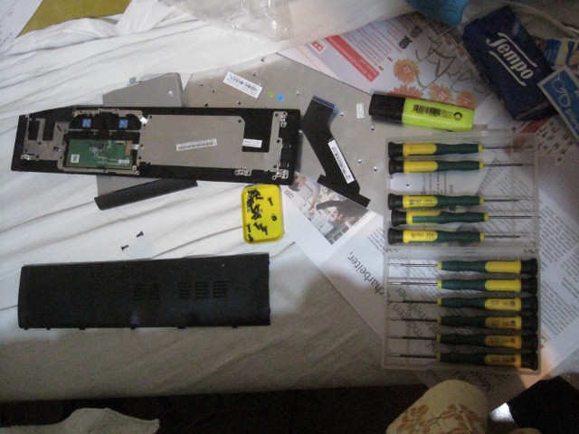
Now cleaning an aperture is not hard, though do NOT try it with this lens if its your first such repair attempt, as this lens is a floating element design, which in laymen terms means complex. The tools you need are just a bunch of small screwdrivers (for most screws the cheapest will do), some paper towels for various things, a clean soft brush to remove dust. And something to clean the aperture blades, probably anything that removes oil would do. And a box of some kind to put all parts in when taking them apart so tiny things are trapped by gravity inside a quickly search-able space and not your whole room. First step is to loosen the screw on the side of the front

After that the top can be unscrewed, the next part is hold in place by a similar screw, loosen it too and unscrew the part, be careful as this exposes the front glass element and if you take it out, only thing you will achieve is getting dust in.

Now you need to remove the 2 screws and the part that holds the front lens group in correct distance/rotational alignment, you do want to take some notes or add markings to get it later back in exactly the same position. As i am lazy i relied on my carefully composed pic above instead of wimpy notes or markings. You also need a good screw driver here as these screws arent easy to loosen even after removing the stuff that holds them in place with aceton. After you removed the 2 screws and that thingy, put the ring that held the front element in place back so the element doesnt escape

Once the glass is secured you unscrew the front group as a whole (you have to turn it in the other direction from what you expect). After unscrewing it you reach the front side of the aperture. And here i believed i could just remove the 3 screws and take it out, but no its not nearly so easy.

So as we cant get it out yet, disassembling of the bottom is next, remove the 3 screws that hold the mount in place, beware there is a spring, a small pin and a metal ring that are more or less loose

The rear lens group is just screwed in and can easily be screwed out, allowing us access to the rear part of the aperture, what the annoying part is we still cannot take it out for proper cleaning.

To move forward next step is to remove the 2 screws and the part that hold the inner rear part in distance and rotational alignment, again take notes and make markings, the rear part is a little fiddly to put back together with markings (aka expect 2-3 minutes for doing that later) without markings, it would probably be fun but not impossible.

Now the inner rear can be screwed out. And hidden you will find 3 holes in the helix, in these holes there are screws that hold the aperture in place, to loosen them take careful note of their original position, or just be lazy and do like I and do exactly 3 full turns, so you can get it back with 3 exact full turns later. It shouldnt ruin the lens if the aperture isnt centered exactly but id guess there was a reason for this odd way to mount it

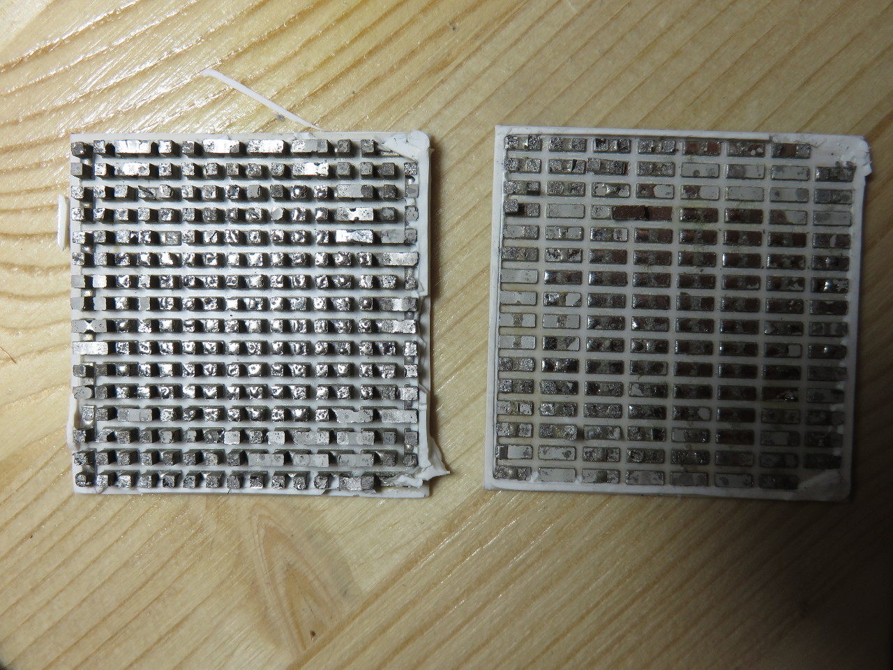
Once the 3 screws are loosened a bit (and a spring is removed) the aperture can be taken out, its further disassembly and reassembly should be obvious. To clean it you can probably use almost anything, i used a little window cleaner in a small container put all parts in and used the “shaken but not stirred” technique, in addition cotton buds and 100% ethanol. Note the pictures below dont look so oily because I tried cleaning it before full disassembly with cotton buds

Once cleaned, reassemble everything, its trivial just reverse of disassembly

From FD to M42 to EOS

The rear FD mount was kept in place by 3 screws, looking a bit around i found a worthless 35mm/2.8 M42 lens laying around that only produces blurry images no matter what, though it was in 100% perfect condition, surely used only once by any previous owner. Its rear fits almost, 2 out of 3 screws can be screwed in without modification. For all 3 a little drilling is needed

With this hack it can be mounted on any M42 camera or with M42-EOS adapter on any canon EOS DSLR. it doesnt focus beyond 1m in that configuration though. That is at 1m real distance you are at infinite on the scale. Also its easy to switch the mounts back :)

Now to get it focus to infinity we need to loose some material, first the M42 rear i picked had a circular ridge that screamed to me “flatten me”

The pic above shows it in the middle of the flattening process. This wasnt enough though, infinity focus still was far away, so the ring that keeps the aperture selection ring in place had to go too. Note, below the next (now loose) ring are 2 loose springs and 2 tiny steel balls dont loose them if you try this. A magnet is a pretty nice way to temporary store them safely.

With this ring too removed infinite focus becomes possible on M42 and EOS. But due to all the removals, one ring holding the aperture selection ring in place and the aperture controlling parts that where part of the FD mount. We still arent done, so next is rebuilding the aperture control parts that a manual lens would have. Ive build it out of a piece of aluminum that i found in a old box from my grandfather, I still remember how my mother wanted to throw all the stuff from him away, lucky i safed a few boxes…

Above picture shows it in partly finished state, it needed more filing and bending before it worked fully smoothly. The removed ring also needs to be replaced. One could have just made it thinner but i dont have the tools to do this exactly and quickly, besides it would make it impossibly to undo it. So i used a piece of plastic cut from a cap of something random from the bathroom, also to get the focus a bit closer to correct (it was way over infinity) i put the thin metal ring from the FD mount back in

And last fine-tuned the focus with the 3 screws intended for that purpose visible at an earlier picture, cleaned the glass a bit and ready is my 24mm f/2 vivitar/kiron for M42 and EOS.

Was the work worth it? For the lens/photography, probably not. For the fun and geek factor, absolutely yes. :)

Filed under: Cameras,Hardware,Reverse Engineering — Michael @ 08:54
« Previous PageNext Page »

Powered by WordPress