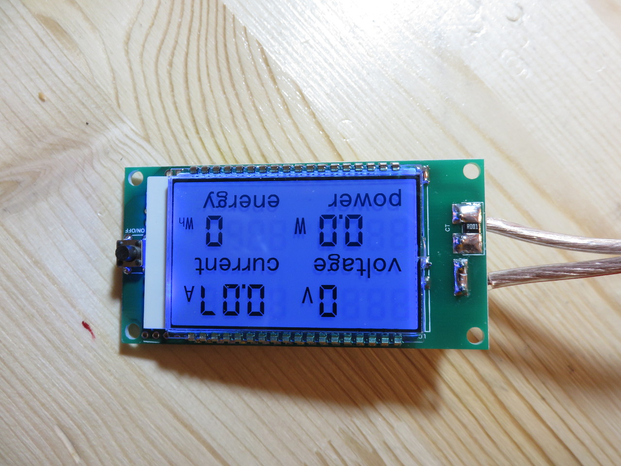
Modifying a 80-250V AC Volt/Amp/Power meter to make it work for 0-250V AC
A while ago i bought an old variac on ebay, it was in good shape but lacked any meter, originally that model had a analog voltmeter or something. That was missing, some cut wires sticking out of where it was. As i got it it also had a 6.5Amp fuse in a fuse holder marked as 4A and its output wires connected straight bypassing the fuse.
When i bought it my plan was to stick a cheap digital meter to it, which is what i did and also a modern and correct “fuse”.
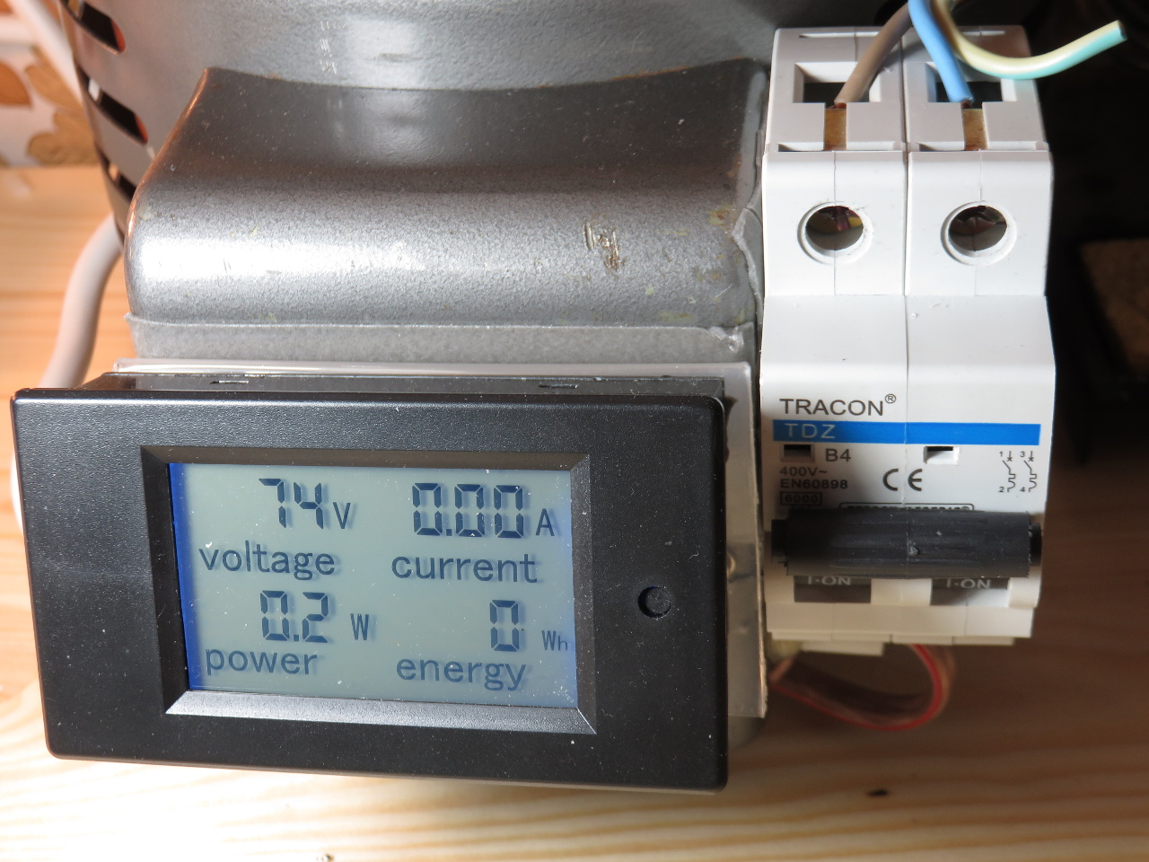
The meter i found and got supported 80-250VAC, i failed to find one supporting AC voltages down to 0V. I originally had not planed to modify it, as it didnt seem a big issue, but it was just annoying that around 70V it dropped out and displayed junk and then went dark.
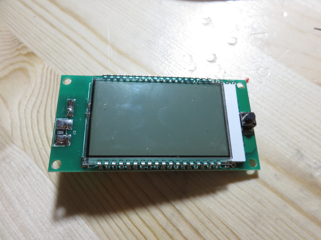
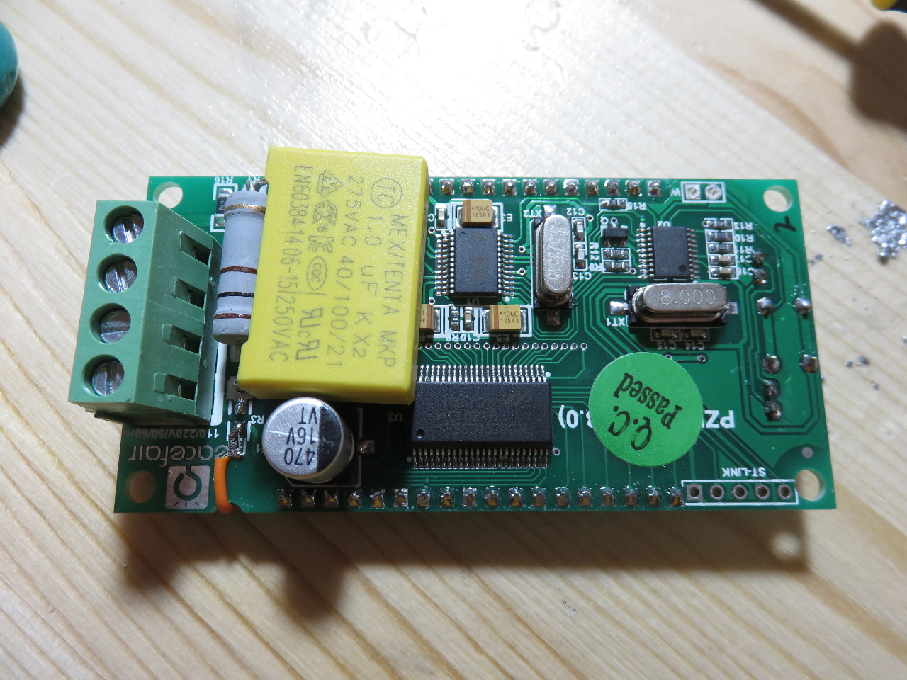
Inside it looks like this:

I saw 2 obvious ways to make this work with lower voltages, first is to make its AC->5vdc supply work with a wider range of AC voltages, the other is to split the voltage sensing off the supply. As my variac provides around 250VAC in addition to the variable and isolated output, using that seemed to be the easier solution.
But before i continue, a warning, do NOT try this unless you understand what you are doing, mains voltage can be dangerous and can injure or kill. Also not all similar looking such meters are neccessary identical and this modification might result in undefined behaviour in that case.
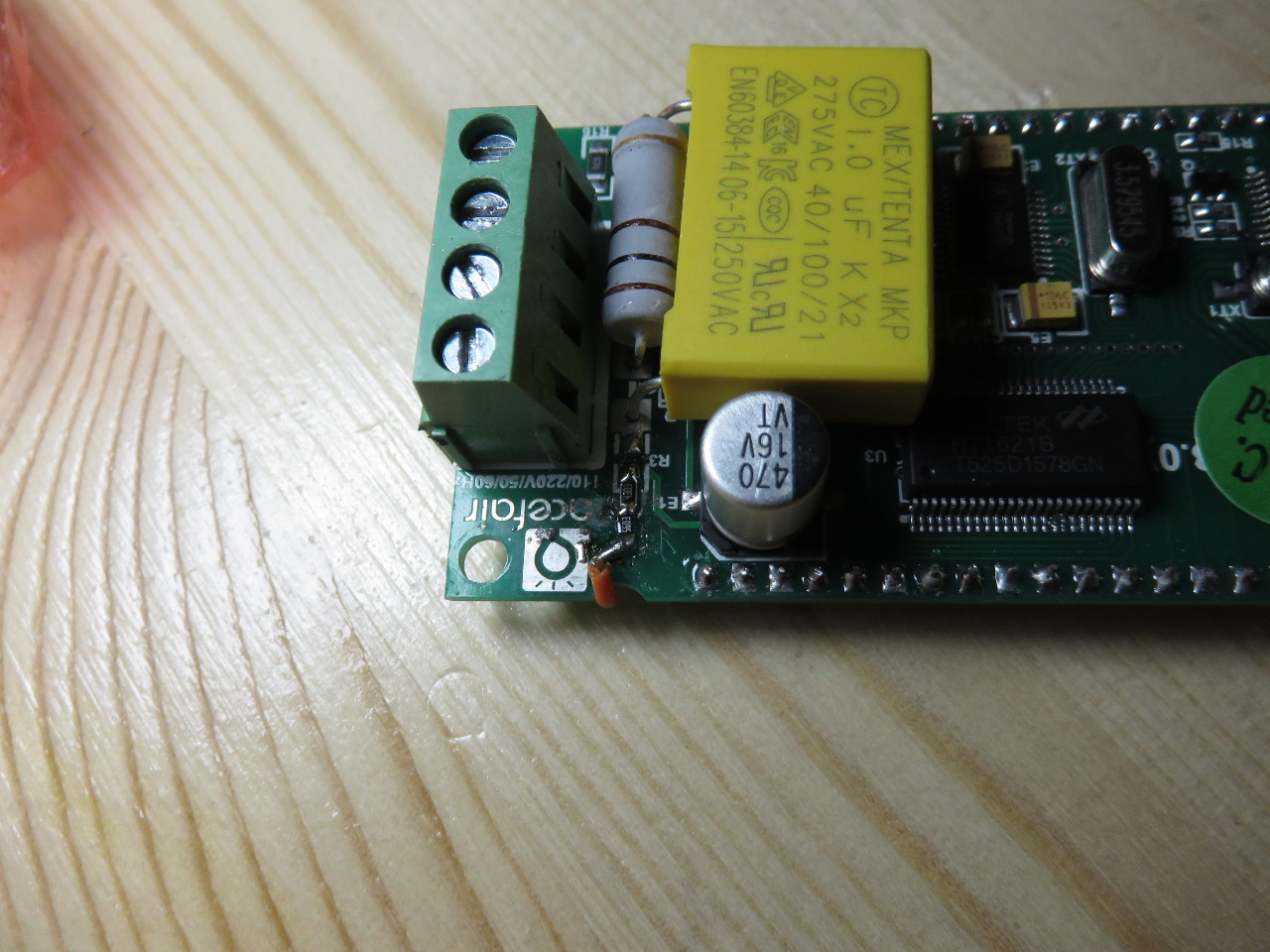
The voltage is sensed through R3 which is 1Mohm, removing it:

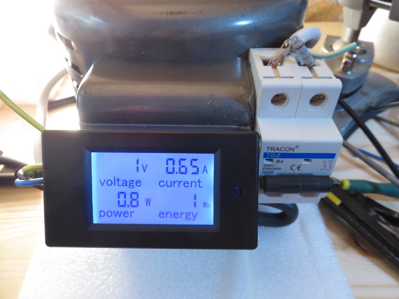
Results in a working amp meter with 0V:
Next we need an additional connector for the separate AC power and AC sense input, to get that we just need to clear 2 from solder and cut the 2 connected pins on the other side using a file. Note, if you try this modification double check that the new freed up pin is not connected to anything else by some tracks below, it wasnt in the meter i had but that doesnt imply its not in yours.

Now its tempting to use the same or a new 1meg ohm resistor for the new sense wire added below (and i did and it worked) but this is probably not safe, first you should clear the conductive parts of the logo which are below, off the board and use 2 resistors in series as there is about 230VAC over it, yes it was already before any modifications but still.
You can also slightly adjust the value of this resistor to adjust/finetune the volt-meter.
The other side of the resistor is connected with a mod wire to the newly freed up pin on the other side. Again using a file to make some cut in the board to nicely route the wire around.

The new connector is then connected like this:
- Variac secondary tap 1
- Variac secondary tap 2 and Load/Output connection A
- Variac secondary tap 3
- Load/Output connection B
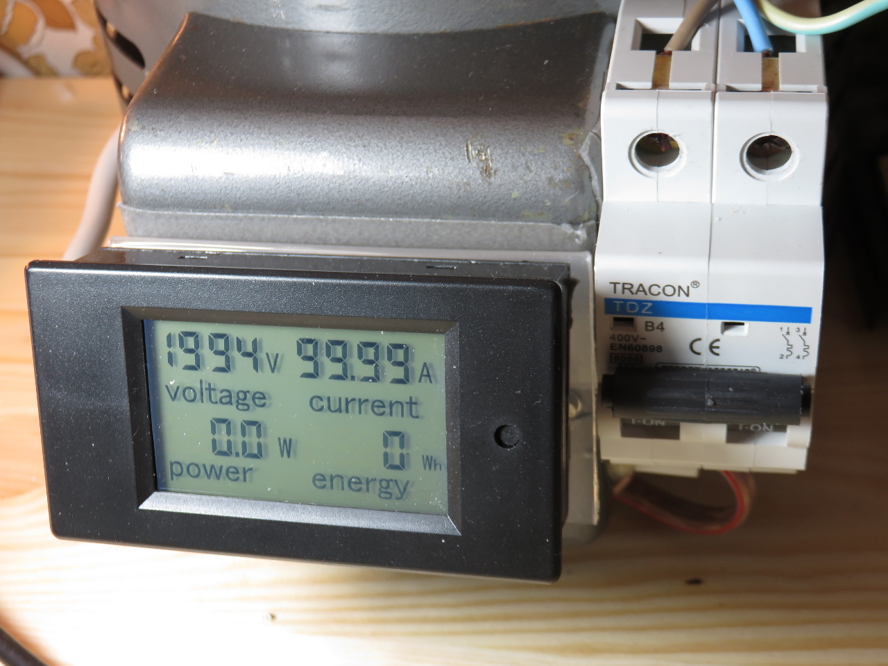
Testing, works: